Link State Information
The link state protocol is a binary protocol that greatly improves message routing in Exchange 2000 over Exchange 5.5. Message routing in Exchange 5.5 is based on the GWART, which is a table that keeps track of each available connector in the Exchange 5.5 organization, along with the cumulative cost of using those connectors. The GWART is limited in that it contains only next-hop information. It doesn't monitor whether the link is actually up or down. The GWART is located in the Site Addressing object and is referenced by the MTA when determining messaging paths to a destination server.
The link state protocol operates over TCP port 691 within the routing group. In each routing group, one server is configured as the routing group master (RGM). The RGM receives link state information and propagates this information to the other servers in the routing group, including the BHS. When one BHS connects to another BHS in a different routing group, the exchange of link state information occurs over TCP port 25, using SMTP. The RGM keeps track of which servers are up and which are down and propagates that information to the RGM in every other routing group.
Link State Algorithm
The link state algorithm is new to Exchange 2000 Server, although it has been around for many years. First developed by Edsger Dijkstra in 1959, it forms the foundation of the Open Shortest Path First (OSPF) protocol, used extensively by routers today. Although Exchange 2000 Server incorporates routes and costs, it also relies heavily on link state information to route messages between routing groups.
The link state algorithm propagates the state of the messaging system almost in real time to all servers in the organization. There are several advantages to this:
- Each Exchange server can make the best routing decision before sending a message downstream where a link might be down.
- Message "ping-pong" is eliminated because alternate route information is propagated to each Exchange 2000 server.
- Message looping is eliminated.
Given the extensibility of this protocol, it is possible that future versions will be able to interact with network routers to achieve even greater routing capabilities. Networks that collaborate in this way are known as directory-enabled networks.
Link State Concepts
Link state information is rather important when an organization has multiple routing groups with multiple paths between the groups. The RGM maintains the link state information, sending it to and receiving it from the RGMs in other routing groups. The RGM is not necessarily the same server as the BHS, which is the server that you designate to send and receive messages across a given connector to another BHS. You can, however, manually configure one server to perform both roles.
The RGM ensures that all the servers in its routing group have correct link state information about the availability of the messaging connectors and servers in other groups. In addition, it ensures that other groups have correct information about its servers.
Link state information is propagated among the servers within a group over SMTP. Between groups, however, link state information is replicated from RGM to RGM over TCP port 25. There are only two states for any given link: up or down. The link state information does not include any connection information, such as whether a link is in a retry state. This information is known only to the server involved in the message transfer.
NOTE
Connectors such as the Lotus cc:Mail Connector, the Microsoft Mail Connector, and other EDK-based connectors will always display their link state information in Exchange System as up, even if the link is unavailable.
Link state information is held in memory, not on disk. If the RGM goes down or needs to be rebooted, it will need to replicate in all current link state information from other RGMs in the organization. Since the routing group information is held in the naming partition of Active Directory, the definitions of connectors and costs are also held in Active Directory. The link state protocol references each connector by its globally unique identifier (GUID).
TIP
When a BHS determines that a link is unavailable, it marks the link as down. It then sends this information to all the servers in its own routing group (over TCP port 691) and to the bridgehead servers in the other routing groups (over TCP port 25). If you are performing a trace for link state data, look for the XLink2state command verb, which denotes this type of data. The information is sent in chunks labeled "first chunk," "second chunk," and so on, up to "last chunk."
Figure 3-12 and 3-13 illustrate what you'll see in Network Monitor. Figure 3-12 shows the link between Folsom and Minneapolis as DOWN. After you restore the link, you can see that Figure 3-13 shows the link as being UP. However, the X-Link2state command doesn't appear in the description of the packet. You'll need to read the data in each packet to find the X-Link2state command packets.
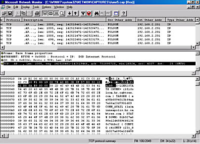
Figure 3-12. Trace showing link state as DOWN.
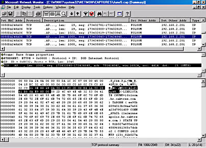
Figure 3-13. Trace showing link state as UP.
How Link State Information Works
Let's look at how link state information works and what happens to messages in the event of a failure. Figure 3-14 shows the topology for a network consisting of five routing groups and indicates the connector cost for each connector. We will assume that all connectors are RGCs.

Figure 3-14. Routing topology for link state example.
Failure of a Single Link
Normally, a message sent from a server in RG1 to a server in RG5 will pass through RG2 and RG4 because it is the route with the least cost. Let's assume, however, that there is a link failure between RG2 and RG4. In this type of single-line failure, the link state protocol causes the routing processes to carry on as follows:
- The BHS in RG1 sends the message to the BHS in RG2.
- The BHS in RG2 attempts to open an SMTP connection to the BHS in RG4. If RG4 contains more than one BHS, the BHS in RG2 attempts to open a connection to each BHS in sequential order.
- The BHS in RG2 is unable to contact any of the BHSs in RG4 because the physical link is down. Therefore, the BHS in RG2 places the connection into a glitch-retry state. The BHS waits for 60 seconds and then attempts to retransfer the message to the BHS in RG4
- After three unsuccessful attempts to connect to RG4, the BHS in RG2 marks the link as down, updates the link state information on the RGM in RG2 over TCP port 691, and makes a call to reroute the message that is sitting in the SMTP out queue.
- The RGM, upon receiving the notification that the link is down, immediately floods this data to all other Exchange 2000 servers in the routing group.
- The BHS in RG2 recalculates an alternate route to RG5 via RG1, RG3, and RG4.
- Before rerouting the message back to RG1, the BHS in RG2 sends the information about the down link to the BHS in RG1. This communication occurs on TCP port 25 and consists of an EHLO command and a X-Link2state command. (For more information on these and other SMTP commands, please see Chapter 17.)
- The BHS in RG1 immediately connects to the RGM in RG1 over TCP port 691 and transfers the information about the down link.
- The RGM in RG1 immediately floods this data to all other Exchange 2000 servers in the routing group.
- Using the new link state information, the BHS in RG1 calculates the best route to RG5, through RG3 and RG4.
- Before routing the message to RG3, the BHS in RG1 propagates the link state information to the BHS in RG3. This process continues until all of the routing groups know of the down link between RG2 and RG4.
It is highly likely that subsequent messages will be sent to RG5 from RG1. When this happens, the messages will be routed through the alternate route (RG1-RG3-RG4-RG5) because each server in the organization knows that the primary route is down.
The BHS in RG2 will continue to try to contact the BHS in RG4 every 60 seconds, even if no messages are awaiting transfer. This value is not configurable. When a link becomes operational again, the new link status is replicated to all of the other Exchange servers in the organization. The BHS transmits the "up" status to the local RGM, which in turn floods the Exchange 2000 servers in the local routing group. Then, similar to the way in which the "down" message was propagated, the "up" message is sent to the rest of the Exchange organization.
NOTE
As Figure 3-15 shows, by default the SMTP virtual server will check the status of the link after 10 minutes for the first retry interval, after 10 minutes for the second retry interval, after 10 minutes for the third retry interval, and then every 15 minutes for each subsequent check. Reduce these intervals if the link is passing mission-critical information between two routing groups. Each retry interval can be as short as 1 minute.

Figure 3-15. Default retry intervals for SMTP virtual server.
CAUTION
In both this example and the next example on multiple link failures, it may seem that link state information is transmitted only immediately ahead of a user-initiated message. This is not the case. Link state information is always transmitted immediately, independently of whether other messages need to be transmitted or not. We mention that the link state information is transmitted ahead of a user's message to indicate the importance that Exchange 2000 Server places on replicating link state information to all its servers. There is no necessary connection or correlation between the transfer of a user-initiated message and the sending of a link state message to another routing group master.
Failure of Multiple Links
If more than one link fails at any given time, the link state protocol ensures that the message doesn't bounce back and forth between routing groups in a continual attempt to find an open message path. Let's look again at the example of a server in RG1 attempting to send a message to a server in RG5. This time, however, let's assume that both the link between RG2 and RG4 and the one between RG3 and RG 4 is unavailable. RG1 sends a message to RG2, and RG2 returns the message to RG1, as it did in our single-link-failure scenario. Here are the steps that the link state protocol will then perform:
- The BHS in RG1 opens a connection to the BHS in RG3. Before sending the message, however, it propagates the down status of the link between RG2 and RG4 to the BHS in RG3. The BHS in RG3 forwards this information to the RGM, which floods the other servers in the routing group with this information.
- Then the BHS in RG1 sends the message to the BHS in RG3. The BHS in RG3 sees that the message is intended for RG5, attempts to open a connection to the BHS server in RG4, and the attempt fails. The BHS server marks the link as being in the glitch-retry state and retries three more times at 60-second intervals.
- If it cannot establish a connection, it marks the link as down and notifies the RGM, which in turn floods the other servers in the routing group with this new information.
- The BHS in RG3 attempts to calculate a new route for the message, given the new information. With both the link between RG2 and RG4 and the link between RG3 and RG4 in the down state, the cost of routing a message to RG5 becomes Infinite.
- Once the cost has been calculated as Infinite, the message remains in the queue of the BHS in RG3, which makes calls to routing, based on the schedule you have configured on the Delivery tab in the property sheet for the SMTP virtual server, to see whether either link has become available.
- When a link becomes available, the message is rerouted as appropriate. If the message stays in the queue for more than 48 hours, it is returned to the sender in RG1 as a nondelivery report (NDR).
If additional messages are sent to RG5 from RG1 while both links are down, the messages remain queued at the BHS in RG1 until one of the links becomes available and a fully functioning route can be established. This is the best place for the messages to remain queued.
NOTE
The 48-hour time period is the default length of time for messages to sit in a queue before a Non-Delivery Report (NDR) is generated and sent back to the user in Exchange 2000 Server. You can configure this value on the Delivery tab of the property sheet for the SMTP virtual server.
Failure of a Routing Group Master
If the RGM goes offline, a new master is not automatically nominated. Therefore, the link state information held by other servers in the routing group could, over time, become increasingly antiquated. If the RGM will be down for a period of time, it is very important that a new RGM be manually configured. This action will ensure that other servers in the routing group have up-to-date link state information.
To manually configure a server to become the RGM, navigate to the routing group in which the server resides, highlight the Members folder for the server, right-click the server in the details pane, and choose Set As Master. Figure 3-16 illustrates this process.
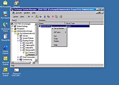
Figure 3-16. Selecting a routing group master in Exchange System Manager.
EAN: N/A
Pages: 193