6.5 Talking Over the Internet
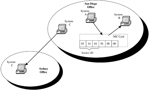
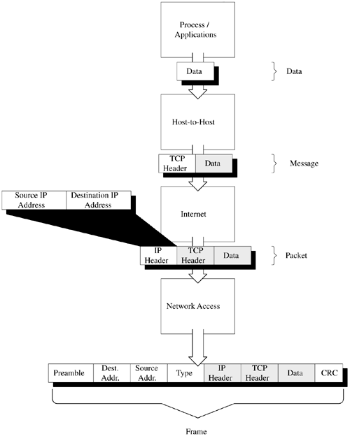
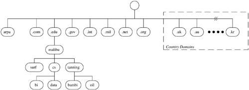
6.5 Talking Over the Internet We now know that a communications protocol establishes the way in which two systems communicate with one another over a network. We also know that TCP/IP is a standard protocol that has become the lingua franca of the Internet. So, what does this mean to us? How does TCP/IP enable us to use something like www.bowlingwithbilly.com to access another system on the network? The answer is something quite amazingamazing that it works. There are three basic elements that we use to accomplish this communication: the hardware address, the TCP/IP address, and the domain name . We will examine each of these in more detail in the following subsections. 6.5.1 HARDWARE ADDRESSWhen we start sending messages around the world, common sense tells us that we need a way to identify the destination of each message. This is the destination address. One would think that the URL above would be sufficient for communication. While text strings work well for people, they really aren't very efficient for systems. We need a way to uniquely identify everything that is sitting on our network. This is where it starts to get amazing. Burned into every Network Interface Card (NIC) is a 6-byte address. The first 3 bytes of that address is the identification number of the manufacturer of the card. Figure 6.3 gives a graphical representation of where hardware addresses fit into this scheme. If we were to remove this card from System A and put it in System B, the hardware address moves with the card. This is true for no matter where we go in the world. If we were to move a system from the San Diego office to the Sydney, Australia, office, the system keeps the same hardware address. How does our protocol use this address to communicate? Figure 6.3. Hardware address. The TCP/IP passes frames between systems. Each frame contains the hardware address of the destination system. Figure 6.4 demonstrates the construction of a TCP/IP frame. The data is passed by the application to the Host-to-Host layer, which in the case of this example is TCP. If we were transferring a file using TFTP, we would be using UDP. TCP adds a TCP header and passes a message to the Internet layer using IP. The Internet layer adds an IP header to the message, creating a packet that is passed to the Network Access layer. Note that the IP Header contains the IP address of the source and destination system. This layer builds a frame that contains the destination and source addresses of the frame. In addition, the Network Access layer adds some control information. By adding this hardware address in the frame, we have identified specifically which NIC on the entire face of the earth is to receive this frame of data. Figure 6.4. TCP/IP frame construction. We now have the two ends of the spectrum. On the one end, we have the hardware address, which is convenient for the computer. The trouble is that the hardware address is not so friendly to people. On the other end, we have a name, like www.bowlingwithbilly.com , something with which people like to deal, but isn't very convenient for computer systems. The next step, therefore, is for us to find a way to map between the two. 6.5.2 DOMAIN NAME SYSTEM (DNS)When we request a file through a Web browser, we're asking for a specific file on a specific computer somewhere on the Internet. To understand this more fully, let's look at an example. Summer is on the way and we want to check out the latest in suntan oil. Naturally, we turn to our dear old alma mater for advice by entering the Uniform Resource Locator (URL) http://oil.tanning.malibuedu/products/study.html in our browser. While it may read like another intimidating piece of computer-ese, compared to a hardware address, the URL has greatly simplified the way we find information on the Internet. The core technology behind the URL is the Domain Name System (DNS), that magical entity that allows us to find a specific computer on the Internet by simply typing its name. The three main components of a URL are shown in Figure 6.5. The first is the protocol. This specifies the protocol we will use when accessing the file on the remote system. The most commonly used protocols are HTTP, HTTPS (HTTP Secure), and FTP. Next is the domain name, which identifies the specific system we wish to access on the Internet. Finally, we have the pathname to the file on that system we wish to access. We can look at this URL and see that we plan to use the HTTP protocol to access the file products/study.html on the computer oil.tanning.malibu.edu . Figure 6.5. Uniform resource locator. Notice that .edu is appended to the end of the system name; this is the generic domain name . The DNS uses this extension to locate the desired computer on the Internet. The DNS is a hierarchy of systems. Figure 6.6 shows the structure of this hierarchy. Each node in the hierarchy is identified by a label that can be up to 63 characters long; names are formed from the bottom up to the root. In our example, we have our alma mater Malibu State. We can see that there are three departments at the school: surfing, computer science, and tanning. The tanning department has two computers, bambi and oil. The computer science department has a database server named data and a computer for business intelligence applications named bi. A fully qualified name is unique throughout the entire Internet and ends with a period. The fully qualified names for these systems would therefore be bambi.tanning.malibu.edu., oil.tanning.malibu.edu., bi.cs.malibu.edu., and data.cs.malibu.edu . Figure 6.6. DNS hierarchy. Names that do not end with a "." are relative domain names and are converted to fully qualified domain names by appending the local domain information. It is unusual to see the "." at the end of a URL. Typically, we end domain names with the generic domain name and the "." is implied . Since the only node in the DNS hierarchy above a generic domain name is the root node, there is little real meaningful difference between the two. We refer to malibu.edu as the domain , the name under which all of Malibu State's computers are registered. The various departments divide the domain into subdomains . Subdomains allow Malibu to have two computers with the same name (remember, we're computer geeks half of our computers are named after Star Trek characters), yet still be identified by different fully qualified names. As we look across this hierarchy, we see the top-level domains displayed under the root node. There are two categories of top-level domains. The first are the generic or organizational domains, such as .com and .edu. These domains, listed in Table 6.1, are also referred to as the U.S. domains. They form the foundation on which all United States-based domain names are built (although some, such as .com, are truly international). Table 6.1. Generic Domains
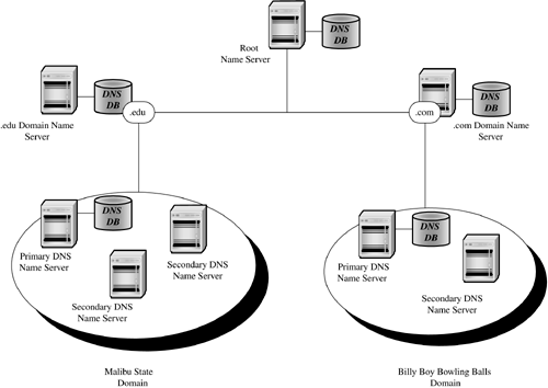
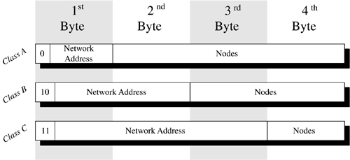
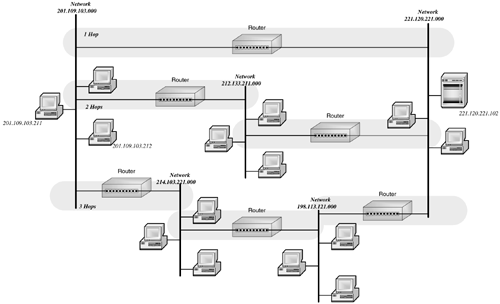
The second group is composed of the geographic domains, such as .uk and .kr (the United Kingdom and Korea respectively). They serve to organize the names of computers residing in the rest of the world. You may note that there is no .US domain. You may also note that we use certain terms interchangeably. In fact, every domain is also a subdomain relative to the top-level domains, and even they are subdomains relative to the root. Fully qualified names are also considered a kind of domain name, except that rather than organizing a network, they designate a computer. As one could therefore imagine, the number of domain names is rather large. Remember, these names include not only the names of all the Web sites on the World Wide Web, but the names of all the computers that are linked to the Internet. If we were to take into consideration just the servers in all the universities in the United States, the number of domain names would be enormous . The solution, of course, is to delegate the administration of parts of the DNS hierarchy. The Internet Corporation for Assigned Names and Numbers (ICANN) accredits companies who in turn are charged with maintaining the top portion of the hierarchy. These registrars are responsible for distributing unique domain names under their assigned top-level domains. A domain may be comprised of a single university, such as Malibu State, or a commercial entity such as bowlingwithbilly.com . Once the domain name is registered, it is the owner's responsibility to create any desired subdomains. To understand how domains are administered, let's refer to Figure 6.7. The administration of a domain requires that a primary name server and one or more secondary name servers be established for the domain. The role of the primary domain server is to maintain a database of host (i.e., computer) names and the IP address of each system identified by those names. These servers receive requests for the IP address of a system with a particular domain name through a domain query. Browsers, for example, generate domain queries to locate Web sites. When the name server receives a query for an IP address, it searches its local database for the domain name. If the server has the IP address, it passes the result back to the requestor . Figure 6.7. Domain administration. Often, the name server is unable to satisfy the request by itself. Each name server in the Internet knows the location of the root or top-level name servers. A root name server contains the name and location of each second-level domain server. For example, the root name server for .edu contains the address of the name server(s) for the malibu.edu domain. When a name server receives a request for a domain name that is not in its database, that name server makes a request of a root name server. The root name server returns the location of a second-level name server. The original name server then queries the second-level name server. This continues for each subdomain ( malibu.edu to tanning.malibu.edu ) until the IP address associated with the fully qualified name is found. The local name server then caches the domain name along with its associated IP address in its local database. In this way, the next request for this name or for any of the subdomains it encountered along the way can be resolved more quickly. 6.5.3 THE IP ADDRESSAlthough we have an address for the computer with which we wish to communicate, we do not have the address we need. There is the natural tendency to wonder why, if we are able to map the fully qualified name to an IP address, don't we cut out the "middle man" and simply map the name to the hardware address. The problem with a hardware address is that it is based on the individual NIC card; there is no relationship between the hardware address and where the system sits on the network. Remember, we can move these systems around at will. The hardware address does nothing to help us locate our destination system. The IP address of a system is a logical address divided into 4 bytes. Anyone who has ever configured a system for network communication is familiar with IP addresses. Typically, we see the IP addresses written in dotted decimal notation, where the IP address is represented as a set of four decimal numbers between 0 and 255. Each decimal number is separated by a period. An IP address might be something like 128.204.122.098. Figure 6.8 shows the structure of an IP address. There are three classes of IP addresses. A zero in the first bit of the 4-byte string indicates a Class A IP address. The first byte of a Class A IP address contains a network address and the remaining three bytes contain the address of a node on that network. Class B addresses are indicated by 10 in the first two bits of the IP address. Class B network addresses are 14-bit long (bits 3 through 8 of byte 1 plus byte 2). The last two bytes of a Class B network contain the node address. Class C addresses are indicated by 11 in the first two bits. The remaining bits in the first byte, plus bytes 2 and 3 contain the network address, with the last byte reserved for the node address. Figure 6.8. IP addressing. The IP address now gives us a way to locate the destination system. We can see how IP addresses are used to locate systems on the Internet in Figure 6.9. Let us assume that the user on the system with the IP address 201.109.103.211 would like to FTP a file to the user on the system with the IP address 201.109.103.212. As the message containing the data is passed from TCP in the Host-to-Host layer to the Internet layer, IP adds the IP header with the destination system's IP address. The Internet layer then uses the Address Resolution Protocol (ARP) to map the IP address to the hardware address on the destination system's NIC. Figure 6.9. Frame routing. ARP maintains a table that maps IP addresses to hardware addresses. When a message is composed with an unknown IP address, a broadcast is sent to all the nodes on the network, requesting that they identify themselves . The hardware address of both the source and destination systems are added to the frame header, and the message is sent to the destination system. This is rather simple if we are all residing on the same network. The challenge occurs when we attempt to communicate with a system on another network. Let's say that now instead of sending the file to a system on the same network, our user wishes to FTP that same file to the server with the IP address 221.120.221.102. Of course, our user identifies the server using its name. DNS provides IP with the IP address of the destination server, which is added to the IP header of the packet. Since the network address of the destination is different than that of the source, we know that we have to send the data through a router. Routers use the Routing Information Protocol (RIP) to keep informed of the different networks to which it is connected. This information is contained within the router's routing table. In addition, the routing table includes the number of hops it takes to get to a particular network. The number of hops indicates how many networks through which the data must pass to reach its ultimate destination. We see in the preceding figure that the message has three alternative routes. After determining the best route for the message, ARP determines the hardware address of the router, which is then placed in the frame header's destination address. When the router receives the frame, it examines the destination address in the IP header to determine the destination. It then creates a new frame with its own hardware address as the source address of the frame. The frame is then passed on to its destination. |
| | |
| Team-Fly |
| Top |
EAN: 2147483647
Pages: 113

