Home Security Surveillance Systems
Home SecuritySurveillance Systems
In this chapter, you will learn about
- Surveillance system basics and design considerations
- Surveillance system components and devices
- Surveillance systems video formats and standards
- Installing a surveillance system
Typically added as an extension of a home security alarm system, a security surveillance system adds the ability for homeowners, or their surveillance monitoring service, to visually monitor their home’s exterior and interior spaces. When used in conjunction with a security alarm system, the homeowner is able to visually scan an area where an alarm has sounded to determine if the problem is in fact a threat or if it is a false alarm. Surveillance systems can also be used in less threatening situations, such as seeing who is ringing the front doorbell, who is knocking on the door, or how the baby is doing in the nursery.
| CROSS-REFERENCE |
See Chapter 31 for more information on security alarm systems. |
In the world of home technology integration, surveillance systems are comprised of cabling, cameras, mounts, monitors, and control systems. In this chapter, we look at each of these devices as well as their standards.
Surveillance System Basics
Video surveillance equipment is a natural extension of home security. However, it isn’t necessary to have a home security system to install video surveillance cameras and equipment.
A video surveillance system uses the same technology used to distribute video images throughout a house, where modulators are used to send video signals from a source such as a VCR or DVD player to any number of televisions. The primary difference between a video surveillance system and a cable or satellite television system is merely the source of the video images. In a security surveillance system, the image source is one or more cameras placed around the interior or exterior of a home.
The general technology that is used in video surveillance systems is referred to as closed-circuit television, or CCTV systems. Because the links in a residential video surveillance system run only between a local camera to a monitor or recording device, the loop is considered a closed loop, or a closed circuit.
Video Surveillance Devices
The primary components of a video surveillance system are
- Video camera
- Video monitor
- Video switchers
- Cabling and connectors
Video Cameras
A video surveillance system can include a wide variety of camera types, including cameras that range in style, focal length, interior versus exterior use, and certainly price, which we won’t be discussing here.
Camera StylesThe type or style of camera used in a home security system depends on its location and the range of view desired. There are five basic camera styles to choose from:
- Board cameraBoard cameras are designed to be used as hidden cameras and to be placed inside household objects, such as walls, books, or other objects where they can be camouflaged. Board cameras are not typically protected for exterior use. Figure 35-1 shows an example of a board camera, also known as a pinhole camera.
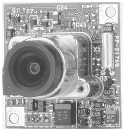
Figure 35-1: A board camera is typically hidden away out of view. - Box cameraThis type of camera gets its name from its shape (see Figure 35-2). The box casing is weatherproof and allows the camera to be mounted on exterior surfaces. Some box models include zoom capabilities.
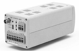
Figure 35-2: A rearview of a box-style security camera showing its connectors
Photo courtesy of Bolide Technology Group.
- Bullet cameraThis type of camera (see figure 35-3) gets it name from its elongated shape. Bullet cameras are commonly used on building exteriors in both home and commercial security systems.
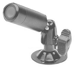
Figure 35-3: A bullet-style security camera - Dome cameraDome cameras are common in stores, casinos, and other commercial installations. Dome cameras are typically capable of pivoting to provide a 360-degree pan view of an area. Dome cameras can be retrofitted into an existing home, but are easier to install during new construction. Figure 35-4 shows an example of a dome camera.
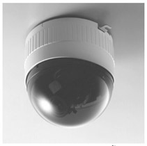
Figure 35-4: A dome camera, which observes an area with a 360-degree sweep, is typically mounted on a ceiling.
Photo courtesy of JVC Professional Products Company.
- PTZ (pan, tilt, and zoom) cameraPan means moving side to side; tilt means moving up and down; and zoom means getting closer to an image and magnifying it. PTZ cameras (shown in Figure 35-5) provide the most flexibility for security cameras. These cameras can be controlled through a manual control, such as a joystick controller or computer software. Some dome cameras have PTZ capabilities, and PTZ bases can be used as mounts for nearly all camera types.
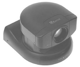
Figure 35-5: A PTZ camera can be controlled to move up and down, side to side, and to produce closer view.
Although they’re only an adaptation of board cameras, another category of cameras you commonly see listed is hidden cameras. These devices are built into such objects as smoke alarms, motion detectors, clocks, exit signs, and the like. Some hidden cameras are also referred to as nanny cams because of their capability to observe household workers and occupants.
Choosing a Security CameraOnce the types of cameras to be used inside and outside a home are selected, the characteristics of these particular cameras must be considered. The four primary features that should be considered for a home surveillance system include the camera’s focal length, light sensitivity rating, lines of resolution, and if it’s color or black and white.
- Focal lengthThe focal length of a camera is the distance (in millimeters) from the lens to the point where the image is in focus. The most common focal range on security cameras is 3.6 millimeters (mm), which typically provides a full view of a room if the camera is mounted in a corner near the ceiling. A longer focal length, such as 6.0mm, provides a greater magnification of images, such as faces, hands, and the like, at a distance.
- Light sensitivityThe light sensitivity of a camera is measured in lux (lumens). One lux is the equivalent of the amount of light produced by one candle measured at a distance of one meter. The lux rating on a camera indicates the minimum of light the camera needs to capture images clearly. Those cameras that have a lux rating of less than 1.0 are capable of capturing images in very dim light. While there are some 0 lux cameras, most security cameras are in the range of 0.1 to 0.8, where less (the lower lux rating) is more (it can capture photo in low light).
- Lines of resolutionThis characteristic measures the number of horizontal lines used to represent the images a camera captures. For example, a standard television set typically has 300 lines of resolution, but video monitors often support many more (800 lines is common). Higher resolution on a camera means that images at a distance are more easily recognizable. A camera that produces a higher number of lines of resolution translates to a better image on the monitor (providing the monitor is capable of reproducing the resolution of the camera). The normal range available is between 300 and 600 lines. However, the better the resolution, the more expensive the camera.
- ColorAnother consideration for choosing a camera is if it’s black and white or color. For most installations, black and white is probably adequate, but some homeowners may wish to install (and pay for) color cameras.
How to Calculate Focal Length
If you wish to have more detail through the lens of a security camera and wish to look for something beyond a 3.6 mm focal length, here's how to go about it (remember, you're insisting on this!):
- Measure the viewing width, the distance between the points you wish to be the left and right extremes of the image viewed. This means measure how wide a field of view you wish to capture. Figure 35-6 illustrates how this is done.
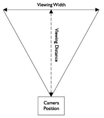
Figure 35-6: Measuring the viewing distance and the viewing depth - From the center of the line between the right and left edges of view, measure the point where the camera lens will be mounted. Figure 35-6 illustrates how the viewing distance is measured.
- Depending on the camera and its format —it should be 1/3-inch, 1/2-inch, or 2/3-inch (also referred to as 1/3 chip, 1/2 chip, and 2/3 chip)—a factor that corresponds to the format is used to adjust for either the horizontal range or the vertical range of the lens. Table 35-1 lists the various horizontal and vertical factors for the common security camera formats.
Table 35-1: Focal Length Calculation Horizontal and Vertical Multipliers Factor
1/3-inch format
1/2-inch format
2/3-inch format
Horizontal (h)
3.6
4.8
6.6
Vertical (v)
4.8
6.4
8.8
- The formula used for calculating focal length is one of the following, depending on whether you wish to use vertical or horizontal adjustment:
Focal length (f) = v * (Viewing distance / Viewing width)
or
Focal length (f) = h * (Viewing distance / Viewing width)
- So, assuming we wish to emphasize the horizontal view of a 1/3-inch format camera and our measurements (in millimeters) are a 380 mm viewing width and an 1800 mm viewing distance, the calculation for the focal length is:
f = 3.6 * (1800 / 380) = 3.6 * (4.8) = 17.3 mm
- The result of 17.3 mm is the focal length desired. Security camera lens are available with focal lengths that typically range from 1.9 mm to 25 mm. The closest lens size to the desired focal length is a 16 mm (f16) lens, but you could move up to an f25 if you wish to improve the viewing range.
Image Capture Formats
Not all cameras are alike. What separates cameras and their capabilities more than any other characteristic is how they capture an image (or in this case video images). The most common camera types used for surveillance purposes are black and white analog cameras, primarily because of their relatively low cost. However, black and white and even color digital cameras are becoming popular for surveillance use as well.
The most common types of cameras used for security surveillance purposes are
- Analog cameras
- Digital cameras
- Infrared cameras
Analog CamerasAnalog cameras use the RS-170 television standard to capture and transmit images as analog signals, and a synchronization pulse supplied by the camera. The transmitted image is created through a sampling process that captures a set number of frames per second (fps) and the position of each feature in a particular frame is determined by the timing between its signal and the synchronizing pulse. A feature called a frame grabber interprets the analog signals and resamples the video images into pixels that are transmitted to the video display device. Analog cameras produce 8-bit resolution, which is able to represent only 256 grayscale shades.
Although commonly referred to as a digital device, another analog image capture device is a CCD (charge coupled device) chip. A CCD chip is light sensitive and captures images in grayscale. Color CCDs uses a RGBG (red, green, blue, and green) mask to provide color images to the display device (the second green is used to create contrast on the image). CCDs are typically connected directly to an analog-to-digital converter (ADC), which provides a digital representation of the captured images.
Digital camerasA digital camera is really an analog camera that has an ADC built in. Because the analog image is converted to digital pixel coding inside the camera, the quality of the signal is improved and the image accuracy is better than on an analog camera.
Digital cameras use a progressive-scan mode to capture images that produce larger image sizes, higher frame rates, and better resolution. Digital cameras are able to produce higher than 8-bit resolutions; 10-bit cameras can produce 1024 grayscale shades; and 12-bit cameras can produce 4096 grayscale shades of resolution. Digital color cameras use 24-bit resolution or the combination of 8-bits each for red, green, and blue color channels.
The connection between the digital camera and the display devices is commonly one of the following formats:
- IEEE 1394Also known as FireWire and iLINK, this link competes with USB (Universal Serial Bus) for ease of use and data transfer speed.
- Parallel interfaceThe most common parallel formats used with digital video cameras are TTL (transistor-to-transistor logic), EIA/TIA (RS) 422, or LVDS (EIA/TIA [RS] 644) signaling formats.
- Parallel TTL (through-the-lens) can only be used with very short cable runs (less than 15 feet) and works best with a TTL-capable monitor and requires a TTL-to-TTL cable.
Note Don’t confuse TTL (through-the-lens) focusing and light metering capabilities on a camera with TTL (transistor-to-transistor logic) signaling.
- EIA/TIA-422 is a differential serial interface that provides greater distances and faster data speeds than the more common EIA/TIA-232 serial interface. LVDS (low-voltage differential signaling) is a gigabit high-speed low-voltage, low-amplitude signaling format for copper wiring.
- USB (Universal Serial Bus) A high-speed serial interface.
- Parallel TTL (through-the-lens) can only be used with very short cable runs (less than 15 feet) and works best with a TTL-capable monitor and requires a TTL-to-TTL cable.
Table 35-2 lists the specifications for each of the above cable standards.
|
Interface |
Conductors |
Cable Requirement |
|---|---|---|
|
IEEE 1394 |
4, 6, or 9 |
Double Shielded 20 - 28 AWG |
|
Parallel |
16 or 18 |
Shielded 22 - 30 AWG |
|
USB |
4 |
Shielded 20 - 28 AWG |
Infrared (IR) CamerasInfrared (IR) cameras use IR light to illuminate the field of view and an analog CCD chip for image capture. In dim or dark lighting conditions, the IR illuminators enhance low-light visibility and allow the CCD to capture images in black and white at low resolution.
IP CamerasAlthough not technically a type of image capture, IP (Internet Protocol) cameras use any image capture technology and have the built-in capability to connect to and communicate over a network running the TCP/IP protocols. Figure 35-7 shows a rearview of an IP-compatible surveillance camera and its RJ-45 connector.
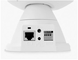
Figure 35-7: An IP camera includes a network jack
Photo courtesy of Veo.
IP cameras have a built-in network adapter, network connectors, and circuitry to support network communications. Connecting an IP camera to a home network allows captured images to be transferred across the data network and be displayed on computer monitors or stored as digital files on networked storage devices.
Wireless CamerasThere are several types of wireless cameras that can be connected into a home surveillance system:
- IP wireless camerasThese type of wireless cameras are designed to connect into wireless Ethernet data networks using the 802.11 wireless networking standards.
- ISM (Industry, Science, and Medical) wireless camerasISM cameras transmit images using the 2.4 GHz radio frequency (RF) band, which is the same band used by many home wireless products, such as cordless telephones.
- PLC “wireless” camerasPLC cameras are wireless only in the sense that they require no new wiring. They operate over the existing electrical lines.
Wireless cameras require a compatible receiver or base unit connected to a computer or a television monitor. In terms of reliability, wired camera systems continue to be more reliable due to potential interference problems with wireless transmitted video signals.
Truly wireless systems either have a wireless transmitter built into the camera itself or connect to a wireless transmission unit or they use a wireless balun-style transmitter (see Figure 35-8). A wireless receiver must be connected to a switcher or monitor. The downside of this type of wireless system is that it typically uses the 2.4 GHz RF band, is the same band used by many other wireless systems in a home, including cordless telephones, baby monitors, and the like.
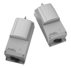
Figure 35-8: A wireless video transmission set connects into the video system for transmitting video signals.
Photo courtesy of Silent Witness Enterprises, Ltd.
Audio-Capable CamerasSeveral surveillance camera models include built-in microphones to pick up sounds from the immediate surrounding areas. Adding audio to the video images captured by the surveillance camera can provide input on activities that may be out of the camera’s range, such as directly beneath the camera.
Cameras that include audio capabilities use triple RCA composite audio/video cabling and connectors.
| CROSS-REFERENCE |
See Chapter 15 for more information about audio cabling and connectors. |
Camera Power Sources
Virtually all CCTV video cameras use either 120V AC or 24V AC power sources.
- 120V ACCommon household AC power is a common power source for video cameras. 120V AC cameras typically come with a 6- to 10-foot power cord, so the camera must have an AC power outlet within that distance.
- 24V ACMost commercial security systems use this voltage, which is usually provided through an external plug-in low-voltage power adapter or power supply that can be some distance from the camera. The power source can be connected to the camera using 18- or 20-gauge speaker wire or using what is called Siamese wire. Siamese wire has a power cable and a coaxial cable inside a single outer jacket. Using a central power source, all wiring can be run up to 350 feet to a central location. However, typically a 24V AC power supply is not provided with the camera and must be purchased separately.
Video Monitors
Essentially, stand-alone video monitors used with video surveillance systems are television sets (see Figure 35-9) that are designed specifically for use as a security system monitor or have a video-in jack to connect directly to a camera or a modulation unit.
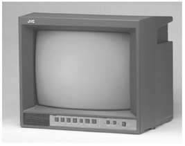
Figure 35-9: A stand-alone television monitor can be integrated into a surveillance system.
Photo courtesy of JVC Professional Products Group.
- Security system monitorsTypically, specialized security system monitors are sold as a part of a complete security system or as an option or extra to a brand-name line of security products designed to work together. These monitors typically have their controls on a front panel and multiple input and output jacks on the back. They typically range in size from 5.5-inches to 13-inches diagonally measured. Some security system monitors also have the capability to display two to four different camera inputs simultaneously using a split-screen technique (see Figure 35-10).
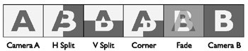
Figure 35-10: The various combinations available from a split-screen system with two camera inputs (cameras A and B). - Video-in TVsAny television that has a video-in jack compatible with the cabling and connectors of a particular video camera can be used as a video surveillance monitor. In cases where the TV is unable to connect directly to a video camera, because of signaling differences primarily, a video signal modulator can be used to convert the signal to a standard TV format (a TV channel) that can be displayed on the monitor.
- Computer monitorsVideo camera signals can also be displayed on a computer monitor if the computer is equipped with the proper interface device or expansion card. IP cameras transmit video images in a format that can be immediately displayed on a computer monitor using video display software. Other signal formats, such as CCTV, CATV (community antenna TV), or NTSC (National Television Standards Committee) must be modulated before they can be displayed on a computer monitor using a external or internal interface device (see Figure 35-11).
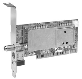
Figure 35-11: A video interface card provides a computer with the ability to receive TV signals.
Photo courtesy of ATI Technologies, Inc.
Modulators
Modulators are devices that convert a video signal from one format to another. In the context of a home video surveillance system, a modulator converts the baseband video signal from the camera into one that is compatible with one or more VHF (very high frequency) or UHF (ultra high frequency) television channels and broadcasts the video image on that channel.
If the homeowner wishes to display the video from a security camera on a specific channel of a television set, a modulator will be needed between the camera and the TV to convert the signal accordingly.
To display a video image, a display device must receive a video signal formatted for the particular signal configuration it displays. Devices with the capability to display a selection of multiple video signal channels (such as a TV) separate the incoming signals based on their modulation. Transmitted video signals are modulated (converted) for a particular channel. When you change the channel on a TV set, you are telling the receiver to display those signals modulated for the channel you want to see.
In a home system, especially one with multiple video source devices, each device must be modulated to a particular channel so it can be displayed on a TV monitor or a computer monitor. To do this, the video signals must be passed through a device called (what else?) a modulator. For a home system, a range of different modulators is available:
- Single channel modulatorsThis type of modulator converts the incoming video signal (from one or more selectable sources) to the format of a single TV channel, typically channel 3 or 4. A good example is a VCR or DVD player. Figure 35-12 shows a single channel modulator.
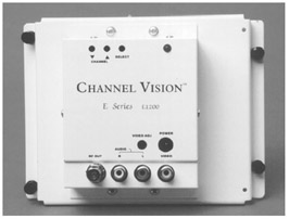
Figure 35-12: A distribution panel mountable single channel modulator
Photo courtesy of ChannelVision.
- Multiple channel modulatorsThis type of modulator accepts multiple input sources and modulates each video input to unique selectable output channels. This type of modulator, shown in Figure 35-13, allows you to select which source device is displayed on which TV channel.
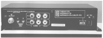
Figure 35-13: A multiple channel video modulator
Photo courtesy of ChannelVision.
- Micro modulatorsThis type of modulator is used with digital video capture devices for display on computer monitors or digital TVs.
Video Switchers and Multiplexers
If a home’s video surveillance system requires more than one camera, whether the cameras are interior or exterior, some form of switching is typically required. A video switcher sequences between multiple cameras to permit viewing or recording from the full-screen display from each camera, one at a time.
SwitchersThere are several types of switchers to choose from for a surveillance system, depending on the number of cameras and the needs of the homeowner:
- Alarming switcherThis type of switcher can be connected to a motion detector or an alarm device and when an alarm signal is detected on that channel, the switcher stops any sequencing and locks onto the camera associated with the alarm. The switcher can also automatically connect the selected camera to a recording device when the alarm signal is detected.
- Bridging sequential switcherThis type of switcher supports two outputs, but typically has multiple inputs. A bridging switcher is able to display two cameras on separate monitors and on some models even sequence multiple cameras on either monitor. Figure 35-14 illustrates the connections used with a bridging switcher.
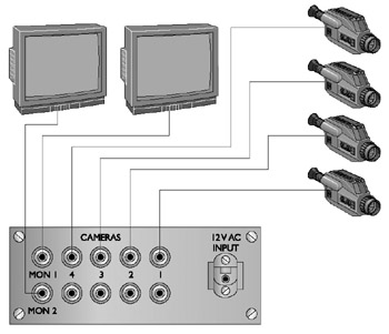
Figure 35-14: The connections used to connect a bridging switcher to multiple devices - Homing switcherThis type of switcher has only one output connection, but can support multiple inputs. This switcher can display or record one camera or multiple cameras in a rotating sequence. Figure 35-15 illustrates the connections used to connect a homing switcher to multiple cameras.
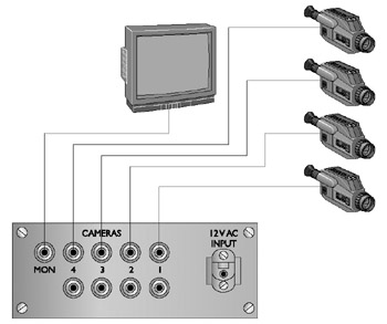
Figure 35-15: The connection pattern used to connect a homing switcher to four cameras and a monitor - Sequential switcherThis type of switcher automatically switches between multiple cameras or video recorders with the capability to record a variable amount of delay between the switching from one unit to the next.
Quadrant Switchers2Another type of specialized video switcher is a quadrant-switcher (quad-switcher) that allows the viewing or recording of up to four cameras on the same screen at one time. If the video signal is recorded, the recorded image is also in quadrant format. Figure 35-16 shows a Pelco monitor that has an integrated quad-switcher built in, and Figure 35-17 illustrates the connections made with a stand-alone quad-switcher.
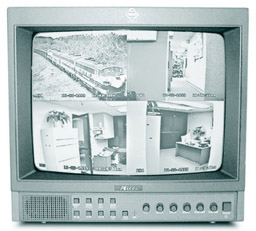
Figure 35-16: A security monitor with an integrated quad-switcher
Photo courtesy of Pelco.
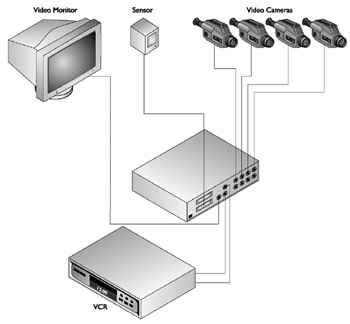
Figure 35-17: The connections used with a stand-alone quadrant-switcher
MultiplexersThere are two types of multiplexers used in video surveillance systems: simplex and duplex. A multiplexer is able to mix and match devices together for display, recording, or playback. It can display one camera on a monitor while another camera is being recorded on a video recorder.
A simplex multiplexer can display one camera while recording all other cameras and a duplex multiplexer is able to display one or more live cameras while recording all other cameras and even displaying playback from a second video recorder.
Cabling and Connectors
Most surveillance systems available on the market are wired systems that use the same standard cabling used in structured wiring schemes. However, there are wireless systems where the camera sends its video signals to a base station using RF signaling. This base station then displays the image or transmits the video signal over wire to the monitor.
Standard Cabling
For most of the connections needed in a video surveillance system, such as from a camera to a monitor, RG6 coaxial cable can be used, provided none of the individual cable runs are more than 200 feet. For distances longer than 200 feet, RG59 coaxial cable, called surveillance video cable, should be used, even though it now is not normally used in home video installations.
Twisted-pair cabling can be used provided a video balun, a device that converts the coaxial cable-compatible signal into one compatible with twisted-pair cabling. A video balun must be installed at each end of the cable run to convert the video signal to and from traveling on the twisted-pair cabling. Figure 35-18 shows a sample of a video balun. Note that one end of the balun has an RJ-45 jack and the other end has a push-on F-type connector.
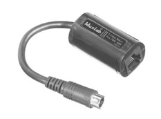
Figure 35-18: A video balun is used to interface coaxial signals to twisted-pair cable.
Photo courtesy of Almex Ltd.
Most security camera kits come with a length of cable for installation, but in a structured cabling environment, the cabling for the surveillance system should be installed during the pre-wire process. If coaxial cable is used, an adapter cable, like the one shown in Figure 35-19, may be required to connect F-type connectors to the camera that may support only an RCA, parallel, or s-video connector. If Cat 5e cabling is used, a balun must be installed at each end of the cable.
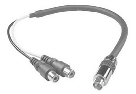
Figure 35-19: A coaxial (S-video) to composite (dual RCA) conversion cable
Photo courtesy of TriangleCables.com
| Note |
Some video security systems use proprietary or special cabling that provides both video transmission from and electrical power to the camera. On these types of systems, the cabling is connected to a single system distribution box that connects into the house AC system. |
Surveillance System Design Considerations
The design of a video surveillance system, like all other residential surveillance systems, must first satisfy the needs of the homeowner and, in this case, involve what the homeowners wish to watch or record inside or outside of their home. Table 35-3 shows a sample of a worksheet used for planning the cameras of a video surveillance system. The worksheet should include not only the cameras, but the monitors and support equipment, such as switchers, multiplexers, and modulators, as well.
|
Location |
Mount |
Type |
Lens |
Wiring |
|---|---|---|---|---|
|
Front Door |
Wall |
Weatherproof |
3.6mm |
Cat5e |
|
Rear Door |
Wall |
Weatherproof |
3.6 mm |
Cat5e |
|
Entry |
Ceiling |
Dome |
Standard |
Cat 5e |
|
Office |
Modulator – 4 channel |
Coaxial |
||
|
Office |
Splitter – 4 channel |
Composite |
||
|
Office |
Monitor – 15-inch |
Composite |
Perhaps the biggest consideration is the layout of the viewing zones, the areas to be covered by the video cameras. In essence, each camera sets up a separate zone for the surveillance system. Are the cameras to be stationary or PTZ? Should any of the viewing zones overlap? Are there areas where a camera may be desired in the futures? It’s these considerations that must be addressed when laying out the plan for the surveillance system.
The next question then is where to place the cameras. What features of the home or exterior should be watched? Gates, doors, windows, and other entry points into the home are the primary targets. If vandalism is a problem, then those areas of the property that are most accessible to vandals should be included. Another consideration is the direction that people (invited or uninvited) face when entering a certain space.
Interior cameras are typically placed either in a ceiling corner of a room or on the ceiling of a passageway. In any case, be sure to include the main entrances and exits from a room or areas in the camera’s view.
Exterior cameras should be weatherproof and if placed in unlighted areas should also include an IR illumination source.
Review
A video surveillance system uses modulators to transmit and convert video signals from source devices to the system’s monitors. The technology used in video surveillance systems is CCTV systems.
The primary components of a video surveillance system are: video cameras, video monitors, video modulators and switchers, and cabling and connectors.
Home security system cameras are available in five basic styles: board cameras, box cameras, bullet cameras, dome cameras, and PTZ cameras. The characteristics that should be considered for a surveillance camera are focal length, light sensitivity, lines of resolution, and color or black and white. The most common types of cameras used for security surveillance purposes are: analog cameras, digital cameras, and infrared cameras. IP cameras have the built-in capability to connect to and communicate over a network running the TCP/IP protocols.
Several types of wireless cameras can be connected into a home surveillance system: IP wireless cameras, ISM wireless cameras, and PLC cameras. Several surveillance camera models include a built-in microphone to pick up sounds from the immediate area around the camera. Virtually all CCTV video cameras use either 120V AC or 24V AC power sources. TV monitors are commonly used with video surveillance systems: security system monitors, video-in TVs, and computer monitors.
For most video surveillance connections, RG6 coaxial cable is used and RG59 can also be used. UTP cabling can be used with a video balun.
The first design consideration of a video surveillance system is the layout of the viewing zones. The next consideration is where to place the cameras. What features of the home or exterior should be watched? Gates, doors, windows, and other entry points into the home are the primary targets. If vandalism is a problem, then those areas of the property that are most accessible to vandals should be included. Another consideration is the direction that people (invited or uninvited) face when entering a certain space.
Interior cameras are typically placed either in a ceiling corner of a room or on the ceiling of a passageway. Exterior cameras should be weatherproof and if placed in unlighted areas should also include an IR illumination source.
Questions
- What is the general technology used in residential video surveillance systems?
- CATV
- HDTV
- CCTV
- FM
- Which of the following is not a primary component of a video surveillance system?
- Cameras
- Monitors
- Sound systems
- Switchers
- Which of the following surveillance camera types is able to pivot, move up and down, and in and out under remote control?
- Board camera
- Box camera
- Bullet camera
- PTZ camera
- Which of the following is not a primary consideration when choosing a video camera for a surveillance system?
- Mounting style
- Focal length
- Light sensitivity
- Lines of resolution
- Which of the following surveillance camera types is able to provide illumination in darkened areas?
- Analog
- Digital
- IR
- RF
- Analog cameras, such as CCDs, convert analog signals to digital signals using which device?
- DAC
- DSP
- CCD
- ADC
- Which of the following is not a common connection type supported by a digital surveillance camera?
- IEEE 1394
- EIA/TIA-422
- USB
- RJ-45
- What are the two voltages most common to residential surveillance systems?
- 12V DC
- 24V DC
- 24V AC
- 120V AC
- What device is typically required in order to display multiple cameras on a single monitor?
- Switcher
- Modulator
- Multiplexer
- Hub
- What is the cabling type most commonly used with video surveillance systems?
- RG-6
- RG-59
- UTP
- Fiber optic
Answers
- C. Closed-circuit television (CCTV) is used primarily for security purposes. CATV is cable television; HDTV is high-definition television; and FM modulation is used with some wireless systems, but typically still within the CCTV system.
- C. Not that sound systems couldn’t be included in a surveillance system, but our focus here is video surveillance. The other choices are all components of a video surveillance system.
- D. Pan, tilt, and zoom cameras are able to be repositioned under remote control. The other choices are typically stationary cameras, unless they are mounted on a PTZ mounting.
- A. If all other features of a camera are desired, the mounting style can be adapted to. However, if the camera application (dome, PTZ, and so on) is not appropriate for the intended use, the other features hardly matter.
- C. Infrared illumination cameras can use IR light to illuminate an area so that the camera can “see” in the dark.
- D. Analog-to-digital converters do just what their name says they do. The other devices are a digital-to-analog converter (DAC), a digital sound processor (DSP), and a charge-coupled device (CCD), which is an image capture device used in video cameras.
- D. By using a balun, a coaxial BNC adapter can be converted to an RJ-45 to send signals over twisted-pair wiring. The other choices are all fairly common camera connector types.
- C and D. Most cameras operate on AC current whether plugged directly into a household current (120V AC) or into an external power supply (24V AC).
- A. Switchers, well, switch. They switch between cameras, monitors, and video recorders either manually or automatically.
- A. RG-6 coaxial cabling is the same coaxial cable used in structured wiring.
Part I - Home Technology Installation Basics
- Wire and Cable Basics
- Connector Types and Uses
- Wiring Installation Practices
- Codes, Standards, and Safety Practices
Part II - Structured Wiring
- Infrastructure Wiring Basics
- Planning a Structured Wiring Installation
- Rough-In Installation
- Trim-Out Installation
- Troubleshooting Structured Wiring
Part III - Home Computer Networks
- Computer Network Basics
- Computer Network Hardware
- Computer Network Software
- Designing and Installing a Computer Network
- Troubleshooting a Home Network
Part IV - Audio/Video Systems
- Distributed Audio System Basics
- Designing and Installing Distributed Audio Systems
- Distributed Video Basics
- Designing and Installing Distributed Video Systems
- Troubleshooting Audio Systems
- Troubleshooting Video Systems
Part V. Home Lighting Management Systems
- Home Lighting Basics
- Home Lighting Devices
- Designing a Home Lighting Control System
- Installing a Home Lighting Control System
- Troubleshooting and Maintaining Lighting Control Systems
Part VI - Telecommunications
- Home Communication System Basics
- Designing and Installing a Home Telephone System
- Troubleshooting a Home Communication System
Part VII - HVAC and Water Management
Part VIII - Security System Basics
- Security System Basics
- Designing a Home Security System
- Installing a Home Security System
- Troubleshooting and Maintaining a Home Security System
- Home Security Surveillance Systems
- Home Access Control Systems
Part IX - Home Technology Integration
- Defining Users Needs and Desires
- User Interfaces
- Home Automation Controllers
- Programming
- Integrating the Connected Home
- Other Home Technology Integration Devices
Part X - Appendices
EAN: N/A
Pages: 300
