10.10 Video coding with the wavelet transform
10.10 Video coding with the wavelet transform
The success of the zero tree in efficient coding of wavelet transform coefficients has encouraged researchers to use it for video coding. Although wavelet-based video coding is not part of the standard, there is no reason why wavelet-based video coding cannot be used in the future. This of course depends on the encoding efficiency of wavelet-based coding and its functionalities. For this reason, in this section we look at some video coding scenarios and examine the encoding efficiency.
One way of wavelet-based video coding is to use the generic video encoder of Figure 3.18, but replacing the DCT with the DWT, as shown in Figure 10.28. Here, variable length coding of the quantised coefficients is replaced by the zero tree coding, of either EZW or SPIHT [18,21]. Also, overlapped motion compensation has been found to be very effective with the wavelet transform, as it prevents the motion compensation blocking artefacts from creating spurious vertical and horizontal edges.
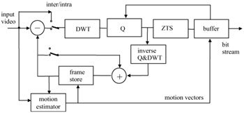
Figure 10.28: Block diagram of a wavelet video codec
Another method that might be used with the wavelet transform is shown in Figure 10.29.
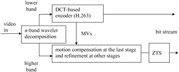
Figure 10.29: A hybrid H.263/wavelet video coding scheme
Each frame of the input video is transformed into n-band wavelet subbands. The lowest LL band is fed into a DCT-based video encoder, such as MPEG-1 or H.263. The other bands undergo a hierarchical motion compensation. First, the three high frequency bands of the last stage are motion compensated using the motion vectors from MPEG-1/H.263. The reconstructed picture from these four bands (LL, LH, HL and HH), which is the next level LL band, only requires a ±1 pixel refinement [20]. The other three bands at this stage are also motion compensated by the same amount. This process is continued for all the bands. Hence at the end all the bands are motion compensated. Now, these motion compensated bands are coded with a zero tree-based coding method (EZW or SPIHT).
10.10.1 Virtual zero tree (VZT) algorithm
The lowest band of the wavelet, LL, is a reduced size replica of the original video, and hence can be encoded with an efficient encoder, such as H.263. When zero tree-based coding such as EZW/SPIHT is used along with the standard codecs (e.g. Figure 10.29), it meets some problems. First, the subband decomposition stops when the top level LL band reaches a size of SIF/QSIF or subQSIF. At these levels there will be too many clustered zero tree roots. This is very common for either static parts of the pictures or when motion compensation is very efficient. Even for still images or I-pictures, a large part of the picture may contain only low spatial frequency information. As a result, at the early stages of the quantisation by successive approximation, where the yardstick is large, a vast majority of the wavelet coefficients fall below the yardstick. Secondly, even if the subband decomposition is taken to more stages, such that the top stage LL is a small picture of 16 x 16 pixels (e.g. Figure 10.28), it is unlikely that many zero trees can be generated. In other words, with a higher level of wavelet decomposition, the tree structure is bound to break and hence the efficiency of EZW/SPIHT is greatly reduced.
To improve the efficiency of zero tree-based coding, we have devised a version of it called virtual zero tree (VZT) [22]. The idea is to build trees outside the image boundary, hence the word virtual, as an extension to the existing trees that have roots in the top stage, so that the significant map can be represented in a more efficient way. It can be imagined as replacing the top level LL band with zero value coefficients. These coefficients represent the roots of wavelet trees of several virtual subimages in normal EZW/SPIHT coding, although no decomposition and decimation actually takes place, as demonstrated in Figure 10.30.
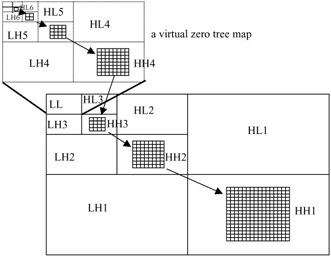
Figure 10.30: A virtual zero tree
In this Figure, virtual trees, or a virtual map, are built in the virtual subbands on the high frequency bands of the highest stage. Several wavelet coefficients of the highest stage form a virtual node at the bottom level of the virtual map. Then in the virtual map, four nodes of a lower level are represented by one node of a higher level in the same way as a zero tree is formed in EZW/SPIHT coding. The virtual map has only two symbols: VZT root or nonVZT root. If four nodes of a 2 x 2 block on any level of a virtual tree are all VZT roots, the corresponding node on the higher level will also be a VZT root. Otherwise this one node of the higher level will be a nonVZT node. This effectively constructs a long rooted tree of clustered real zero trees. One node on the bottom level of the virtual map is a VZT root only when the four luminance coefficients of a 2 x 2 block and their two corresponding chrominance coefficients on the top stage wavelet band are all zero tree roots. Chrominance pictures are also wavelet decomposed and, for a 4:2:0 image format, four zero tree roots of the luminance and one from each chrominance can be made a composite zero tree root [22].
10.10.2 Coding of high resolution video
A wavelet transform can be an ideal tool for coding of high resolution pictures or video. This is because the high correlation among the dense pixels of high resolution pictures is better exploited if a larger area for decorrelation of pixels is used. Unfortunately, in the standard video codecs, the DCT block sizes are fixed at 8 × 8, and hence pixel correlation beyond eight-pixel distances cannot be exploited. On the other hand, in the wavelet transform, increasing the number of decomposition levels means decorrelating the pixels at larger distances if so desired.
We have tested the encoding efficiency of the wavelet transform (for Figure 10.29) for high definition video (HDTV) as well as the super HDTV (SHD). For HDTV, we have used the test sequence Gaynor (courtesy of BBC). For this image sequence, a two-stage (seven-band) wavelet transform is used and the LL band of the SIF size was MPEG-1 coded. Motion compensated higher bands were coded with VZT and EZW. For the SHD video, a park sequence with 2048 x 2048 pixels at 60 Hz (courtesy of NHK Japan [21]) was used. The SHD images after three-stage subband decomposition result in ten bands. The LL band, with picture resolutions of 256 x 256 pixels, is MPEG-1 coded; the remaining nine bands are VZT and EZW coded in two separate experiments.
It appears at first that, by creating virtual nodes, we have increased the number of symbols to be coded, and hence the bit rate tends to increase rather than to decrease. However, these virtual roots will cluster the zero tree roots into a bigger zero tree root, such that instead of coding these roots one by one, at the expense of a large overhead by a simple EZW, we can code the whole cluster by a single VZT with only a few bits. VZT is more powerful at the early stages of encoding, where the vast majority of top stage coefficients are zero tree roots. This can be seen from Table 10.2, where a complete breakdown of the total bit rate required to code a P-picture of the park sequence by both methods is given.
| VZT (kbits) | EZW (kbits) | |||||||
|---|---|---|---|---|---|---|---|---|
| virtual pass | real pass | dominant pass | subordinate pass | sum | dominant pass | subordinate pass | sum | |
| MPEG | _ | _ | _ | _ | 171 | _ | _ | 171 |
| MV | _ | _ | _ | _ | 15 | _ | _ | 15 |
| Pass-1 | 1.5 | 3.2 | 4.4 | 0.16 | 4.9 | 25 | 0.16 | 25 |
| Pass-2 | 7.7 | 31 | 39 | 1.7 | 41 | 153 | 1.7 | 156 |
| Pass-3 | 18 | 146 | 164 | 11 | 175 | 465 | 11 | 476 |
| Pass-4 | 29 | 371 | 400 | 41 | 441 | 835 | 41 | 896 |
| Pass-5 | 42 | 880 | 992 | 128 | 1050 | 1397 | 128 | 1326 |
| Grand total | 1898 | 3265 | ||||||
The first row of the Table shows that 171 kbits are used to code the LL band by MPEG-1. The second row shows that 15 kbits is used for the additional ±1 pixel refinement in all bands. For the higher bands the image is scanned in five passes, where the bits used in the dominant and subordinate passes of VZT and EZW are shown. In VZT the dominant pass is made up of two parts: one used in coding of the virtual nodes and the other parts for real data in the actual nine bands. Note that although some bits are used to code the virtual nodes (are not used in EZW), the total bits of the dominant pass in VZT is much less than for EZW. The number of bits in the subordinate passes, which codes the real subordinate data, is the same for both methods. In the Table the grand total is the total number of bits used to code the P-frame under the two coding schemes. It can be seen that VZT requires two-thirds of the bit rate required by EZW.
For HDTV, our results show that, although a good quality video at 18 Mbit/s can be achieved under EZW, VZT only needs 11 Mbit/s [22].
10.10.3 Coding of low resolution video
Although coding of low spatial resolution (e.g. QCIF, subQCIF) video may not benefit from wavelet decomposition to the extent that higher resolution video does, nevertheless zero tree coding is efficient enough to produce good results. In fact, the multiresolution property of wavelet-based coding is a bonus that the DCT-based coding most suffers from. In section 8.5.7, we saw that two-layer spatial and SNR scalability of the standard codecs (MPEG, H.263) reduces the compression efficiency by as much as 30 per cent. That is, spatial/SNR coders are required to generate about 30 per cent more bits to be able to produce the same video quality as a single layer coder does. Undoubtedly, increasing the number of layers, or combining them in a hybrid form, will widen this deficiency gap.
On the other hand, with the wavelet transform, as the number of decomposition levels increases, the encoding efficiency increases too. Moreover, with the concept of virtual zero tree a large area of static parts of the picture can be grouped together for efficient coding, as we have seen from the results of higher resolution pictures of the previous section.
To compare the quality of wavelet-coded video (purely wavelet-based video codec of Figure 10.28) against the best of the standard codec, we have coded 10 Hz QCIF size of Akio and Carphone standard video test sequences at various bit rates, as shown in Figure 10.31, for Akio and Figure 10.32 for Carphone.

Figure 10.31: Quality of QCIF size Akio sequence coded at various bit rates
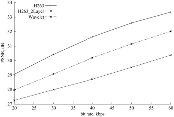
Figure 10.32: Quality of QCIF size Carphone sequence coded at various bit rates
For the wavelet coder, we have used three levels of wavelet decomposition (ten bands) and two levels of virtual nodes, with an SPIHT-type zero tree coding, called virtual SPHIT [23]. Unlike Figure 10.29, where the lowest subband was coded by an standard DCT codec, here we have coded all the bands, including the LL band with the virtual SPIHT (Figure 10.28). This is because, after three-level wavelet decomposition, the lowest LL band has a dimension of 22 × 18 pixels which is not viable, nor practical to be coded with codecs using 16 × 16 pixel macroblocks. On the motion compensation, the whole QCIF image was motion compensated with an overlapped block matching algorithm, with half a pixel precision. Motion compensated wavelet coefficients after the zero tree scan were arithmetic coded.
For comparison we have also coded these sequences with single and two-layer SNR scalable H.263 codecs, at various bit rates from 20 kbit/s up to 60 kbit/s. For the two-layer H.263, 50 per cent of the total bits were assigned to the base layer. As the PSNR Figures 10.31 and 10.32 show, single-layer H.263 is consistently better than the wavelet which itself is better than the two-layer H.263. However, subjectively wavelet-coded video appears better than single layer H.263, despite being 1–2 dB poorer on the PSNR.
Figures 10.33 and 10.34 show snap shots of Akio and Carphone, coded at 20 kbit/s and 40 kbit/s, respectively. Although these small pictures may not show the subjective quality differences between the two codecs, the fact is that the H.263 picture is blocky but that of the wavelet is not. In the Carphone picture, the wavelet-coded picture is smeared but it is still much sharper than the two-layer H.263. Some nonexperts prefer the smeared picture to the blocky one, but expert viewers have a different opinion. Comparing the wavelet with the two-layer H.263, both subjective and objective results are in favour of the wavelet.

Figure 10.33: A snap shot of Akio coded at 20 kbit/s, 10 Hz (a H.263) (b SNR-scalable H.263) (c wavelet SPIHT)

Figure 10.34: A snap shot of Carphone coded at 40 kbit/s, 10 Hz (a H.263) (b SNR-scalable H.263) (c wavelet SPIHT)
Considering that the above three-level decomposition wavelet transform can be regarded as an N-layer video without impairing its compression efficiency, it implies that the wavelet has a high potential for multilayer coding of video. Although this video codec is not a part of any standard, there is no doubt that its high potential for multilayer coding makes it very attractive.
EAN: 2147483647
Pages: 148