8.4 MPEG-2 nonscalable coding modes
8.4 MPEG-2 nonscalable coding modes
This simple nonscalable mode of the MPEG-2 standard is the direct extension of the MPEG-1 coding scheme with the additional feature of accommodating interlaced video coding. The impact of the interlaced video on the coding methodology is that interpicture prediction may be carried out between the fields, as they are closer to each other. Furthermore, for slow moving objects, vertical pixels in the same frame are closer, making frame prediction more efficient.
As usual we define the prediction modes on a macroblock basis. Also, to be in line with the MPEG-2 definitions, we define the odd and the even fields as the top and bottom fields, respectively. A field macroblock, similar to the frame macroblock, consists of 16 x 16 pixels. In the following, five modes of prediction are described [3]. They can be equally applied to P and B-pictures, unless specified otherwise.
Similar to the reference model in H.261, software-based reference codecs for laboratory testing have also been considered for MPEG-1 and 2. For these codecs, the reference codec is called the test model (TM), and the latest version of the test model is TM5 [8].
8.4.1 Frame prediction for frame pictures
Frame prediction for frame pictures is exactly identical to the predictions used in MPEG-1. Each P-frame can make a prediction from the previous anchor frame, and there is one motion vector for each motion compensated macroblock. B-frames may use previous, future or interpolated past and future anchor frames. There will be up to two motion vectors (forward and backward) for each B-frame motion compensated macroblock. Frame prediction works well for slow to moderate motion as well as panning over a detailed background.
8.4.2 Field prediction for field pictures
Field prediction is similar to frame prediction, except that pixels of the target macroblock (MB to be coded) belong to the same field. Prediction macroblocks also should belong to one field, either from the top or the bottom field. Thus for P-pictures the prediction macroblock comes from the two most recent fields, as shown in Figure 8.4. For example, the prediction for the target macroblocks in the top field of a P-frame, TP, may come either from the top field, TR, or the bottom field, BR, of the reference frame.
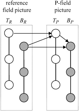
Figure 8.4: Field prediction of field pictures for P-picture MBs
The prediction for the target macroblocks in the bottom field, BP, can be made from its two recent fields, the top field of the same frame, TP, or the bottom field of the reference frame, BR.
For B-pictures the prediction MBs are taken from the two most recent anchor pictures (I/P or P/P). Each target macroblock can make a forward or a backward prediction from either of the fields.
For example in Figure 8.5 the forward prediction for the bottom field of a B-picture, BB, is either TP or BP, and the backward prediction is taken from TF or BF. There will be one motion vector for each P-field target macroblock, and two motion vectors for those of B-fields.
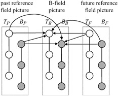
Figure 8.5: Field prediction of field pictures for B-picture MBs
8.4.3 Field prediction for frame pictures
In this case the target macroblock in a frame picture is split into two top field and bottom field pixels, as shown in Figure 8.6. Field prediction is then carried out independently for each of the 16 x 8 pixel target macroblocks.
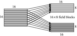
Figure 8.6: A target macroblock is split into two 16 × 8 field blocks
For P-pictures, two motion vectors are assigned for each 16 × 16 pixel target macroblock. The 16 × 8 predictions may be taken from either of the two most recently decoded anchor pictures. Note that the 16 x 8 field prediction cannot come from the same frame, as was the case in field prediction for field pictures.
For B-pictures, due to the forward and the backward motion, there can be two or four motion vectors for each target macroblock. The 16 × 8 predictions may be taken from either field of the two most recently decoded anchor pictures.
8.4.4 Dual prime for P-pictures
Dual prime is only used in P-pictures where there are no B-pictures in the GOP. Here only one motion vector is encoded (in its full format) in the bit stream together with a small differential motion vector correction. In the case of the field pictures two motion vectors are then derived from this information. These are used to form predictions from the two reference fields (one top, one bottom) which are averaged to form the final prediction. In the case of frame pictures this process is repeated for the two fields so that a total of four field predictions are made.
Figure 8.7 shows an example of dual prime motion compensated prediction for the case of frame pictures. The transmitted motion vector has a vertical displacement of three pixels. From the transmitted motion vector two preliminary predictions are computed, which are then averaged to form the final prediction.
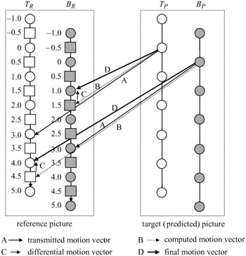
Figure 8.7: Dual prime motion compensated prediction for P-pictures
The first preliminary prediction is identical to the field prediction, except that the reference pixels should come from the previously coded fields of the same parity (top or bottom fields) as the target pixels. The reference pixels, which are obtained from the transmitted motion vector, are taken from two fields (taken from one field for field pictures). In the Figure the predictions for target pixels in the top field, TP, are taken from the top reference field, TR. Target pixels in the bottom field, BP, take their predictions from the bottom reference field, BR.
The second preliminary prediction is derived using a computed motion vector plus a small differential motion vector correction. For this prediction, reference pixels are taken from the parity field opposite to the first parity preliminary prediction. For the target pixels in the top field TP, pixels are taken from the bottom reference field BR. Similarly, for the target pixels in the bottom field BP, prediction pixels are taken from the top reference field TR.
The computed motion vectors are obtained by a temporal scaling of the transmitted motion vector to match the field in which the reference pixels lie, as shown in Figure 8.7. For example, for the transmitted motion vector of value 3, the computed motion vector for TP would be 3 × 1/2 = 1.5, since the reference field BR is mid way between the top reference field and the top target field. The computed motion vector for the bottom field is 3 x 3/2 = 4.5, as the distance between the reference top field and the bottom target field is three fields (3/2 frames). The differential motion vector correction, which can have up to one half pixel precision, is then added to the computed motion vector to give the final corrected motion vector.
In the Figure the differential motion vector correction has a vertical displacement of -0.5 pixel. Therefore the corrected motion vector for the top target field, TP, would be 1.5 - 0.5 = 1, and for the bottom target field it is 4.5 - 0.5 = 4, as shown with thicker lines in the Figure.
For interlaced video the performance of dual prime prediction can, under some circumstances, be comparable to that of B-picture prediction and has the advantage of low encoding delay. However, for dual prime, unlike B-pictures, the decoded pixels should be stored to be used as reference pixels.
8.4.5 16 x 8 motion compensation for field pictures
In motion compensation mode, a field of 16 × 16 pixel macroblocks is split into upper half and lower half 16 × 8 pixel blocks, and a separate field prediction is carried out for each. Two motion vectors are transmitted for each P-picture macroblock and two or four motion vectors for the B-picture macroblock. This mode of motion compensation may be useful in field pictures that contain irregular motion. Note the difference between this mode and the field prediction for frame pictures in section 8.4.3. Here a field macroblock is split into two halves, and in the field prediction for frame pictures a frame macroblock is split into two top and bottom field blocks.
Thus the five modes of motion compensation in MPEG-2 in relation to field and frame predictions can be summarised in Table 8.3.
| Motion compensation mode | Use in field pictures | Use in frame pictures |
|---|---|---|
| Frame prediction for frame pictures | no | yes |
| Field prediction for field pictures | yes | no |
| Field prediction for frame pictures | no | yes |
| Dual prime for P-pictures | yes | yes |
| 16 × 8 motion compensation for field pictures | yes | no |
8.4.6 Restrictions on field pictures
It should be noted that field pictures have some restrictions on I, P and B-picture coding type and motion compensation. Normally, the second field picture of a frame must be of the same coding type as the first field. However, if the first field picture of a frame is an I-picture, then the second field can be either I or P. If it is a P-picture, the prediction macroblocks must all come from the previous I-picture, and dual prime cannot be used.
8.4.7 Motion vectors for chrominance components
As explained, the motion vectors are estimated based on the luminance pixels, hence they are used for the compensation of the luminance component. For each of the two chrominance components the luminance motion vectors are scaled according to the image format:
-
4:2:0 both the horizontal and vertical components of the motion vector are scaled by dividing by two
-
4:2:2 the horizontal component of the motion vector is scaled by dividing by two; the vertical component is not altered
-
4:4:4 the motion vector is unmodified.
8.4.8 Concealment motion vectors
Concealment motion vectors are motion vectors that may be carried by the intra macroblocks for the purpose of concealing errors should transmission error result in loss of information. A concealment motion vector is present for all intra macroblocks if, and only if, the concealment_motion_vectors flag in the picture header is set. In the normal course of events no prediction is formed for such macroblocks, since they are of intra type. The specification does not specify how error recovery shall be performed. However, it is a recommendation that concealment motion vectors should be suitable for use by a decoder that is capable of performing the function. If concealment is used in an I-picture then the decoder should perform prediction in a similar way to a P-picture.
Concealment motion vectors are intended for use in the case where a data error results in information being lost. There is therefore little point in encoding the concealment motion vector in the macroblock for which it is intended to be used. This is because, if the data error results in the need for error recovery, it is very likely that the concealment motion vector itself would be lost or corrupted. As a result the following semantic rules are appropriate:
-
For all macroblocks except those in the bottom row of macroblocks concealment motion vectors should be appropriate for use in the macroblock that lies vertically below the macroblock in which the motion vector occurs.
-
When the motion vector is used with respect to the macroblock identified in the previous rule a decoder must assume that the motion vector may refer to samples outside of the slices encoded in the reference frame or reference field.
-
For all macroblocks in the bottom row of macroblocks the reconstructed concealment motion vectors will not be used. Therefore the motion vector (0,0) may be used to reduce unnecessary overhead.
EAN: 2147483647
Pages: 148