6.4 Quantisation and coding
6.4 Quantisation and coding
Every one of the six blocks of a selected MB is transform coded with a two-dimensional DCT. The DCT coefficients of each block are then quantised and coded. In section 3.2 we described two types of quantiser: the one without a dead zone which is used for quantising the DC coefficient of intra MB, for the H.261 standard, this quantiser uses a fixed step size of eight; the second type is with a dead zone for coding AC coefficients and the DC coefficient of interframe coded MB (MC or NO_MC).
For the latter case, a threshold, th, may be added to the quantiser scale, such that the dead zone is increased, causing more zero coefficients for efficient compression. Figure 6.9 shows this quantiser, where a threshold, th, is added to every step size. The value of the threshold is sent to the receiver as side information (see Figure 6.3). Ratios of the quantised coefficients to the quantiser step size, called indices, are to be coded.
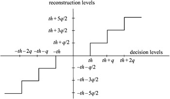
Figure 6.9: A uniform quantiser with threshold
6.4.1 Two-dimensional variable length coding
For transmission of the quantisation parameters, a special order is defined which increases the efficiency of capturing the nonzero components. Starting from the DC coefficient on the top left corner of an 8 × 8 coefficient matrix, the values are scanned in a zigzag sequence as shown in Figure 6.10.
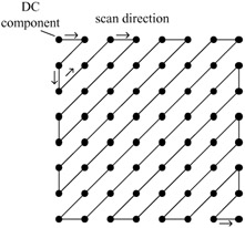
Figure 6.10: Zigzag scanning of 8 × 8 transform coefficients
The justification for this is that in natural images the main energy of the transform coefficients is concentrated in the lower frequencies (top left corner). Hence the coefficients which normally have the larger values are scanned first. Scanning of the indices terminates when the last nonzero coefficient has been reached.
To increase the coding efficiency a two-dimensional variable length code (2D-VLC) has been adopted. The 2D-VLC is performed in two stages. In the first stage, an event is produced for every nonzero index. The event is a combination of the index magnitude (index) and the number of zeros preceding that index (run).
To see how a two-dimensional index and run generation makes 2D-VLC coding very efficient, the following example is based on a coder having a quantiser step size of q = 16 with equal threshold levels th = q. Let us assume a pixel block is DCT coded with coefficient values as shown partly in Figure 6.11.
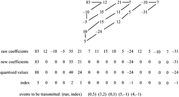
Figure 6.11: Zigzag scanning and run-index generation
After zigzag scanning, coefficients are quantised. For a dead zone of th = 16, coefficient values less than this threshold are set to zero. Larger values are quantised according to the quantisation characteristics (see Figure 6.9). Here we see that rather than 1D-VLC coding of 17 individual coefficients we need to code only five two-dimensional events, which requires substantially fewer bits.
In this 2D-VLC, since the range of index (possible values of indices) can vary from -127 to +127, and the range of run (number of zeros preceding an index) may vary from 0 to 63, there will be 2 × 128 × 64 = 16 384 possible events. Design of a Huffman code for this large number of symbols is impractical. Some codewords might be as long as 200 bits! Here we use what might be called a modified Huffman code. In this code, all the symbols with small probabilities are grouped together and are identified with an ESCAPE symbol. The ESCAPE symbol has a probability equal to the sum of all it represents. Now the most commonly occurring events and the ESCAPE symbol are encoded with variable length codes (Huffman code) in the usual way. Events with low probabilities are identified with a fixed length run and index, appended to the ESCAPE code. The end of block code (EOB) is also one of the symbols to be variable length coded.
In H.261, ESCAPE is six bits long (i.e. 000001), thus rare events with six bits run (0–63) and eight bits index (-127 to +127) require 20 bits [1]. The EOB code is represented with a two-bit word. The DC/intra index is linearly quantised with a step size of eight and no dead zone. The resulting value is coded with an eight-bit resolution.
Figure 6.12 shows an example of a 2D-VLC table for positive values of indices, derived from statistics of coding the Claire test image sequence. As we see, most frequent events are registered at low index and low run values. The sum of the rare events, which represents the frequency of the ESCAPE, is even less than some frequent events. The corresponding 2D-VLC table is also shown next to the frequency table. Also in this example the sum has the same frequency as the event (run = 4, index = 1).
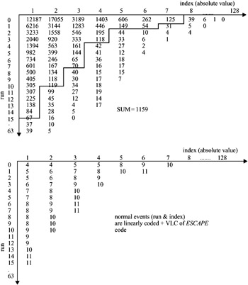
Figure 6.12: An example of run and index frequency and the resulting 2D-VLC table
They are expected to have the same word length. Other events can be defined as ESCAPE + normal run + normal index, with:
-
ESCAPE code = 6 bits,
-
normal run = 6 bits (1 out of 64 possible values)
-
normal index = 8 bits (1 out of 128 values) plus the sign bit
-
total bits for the modified Huffman coded events = 6 + 6 + 8 = 20
EAN: 2147483647
Pages: 148