5.4 JPEG2000 encoder
5.4 JPEG2000 encoder
The JPEG2000 standard follows the generic structure of the intraframe still image coding introduced for the baseline JPEG. That is, decorrelating the pixels within a frame by means of transformation and then quantising and entropy coding of the quantised transform coefficients for further compression. However, in order to meet the design requirements set forth in section 5.3, in addition to the specific requirements from the transformation and coding, certain preprocessing on the pixels and post processing of the compressed data is necessary. Figure 5.10 shows a block diagram of a JPEG2000 encoder.
![]()
Figure 5.10: A general block diagram of the JPEG2000 encoder
In presenting this coder, we only talk about the fundamentals behind this standard. More details can be found in the ISO standardisation documents and several key papers [9–11].
5.4.1 Preprocessor
Image pixels prior to compression are preprocessed to make certain goals easier to achieve. There are three elements in this preprocessor.
5.4.1.1 Tiling
Partitioning the image into rectangular nonoverlapping pixel blocks, known as tiling, is the first stage in preprocessing. The tile size is arbitrary and can be as large as the whole image size down to a single pixel. A tile is the basic unit of coding, where all the encoding operations, from transformation down to bit stream formation, are applied to tiles independent of each other. Tiling is particularly important for reducing memory requirement and, since they are coded independently, any part of the image can be accessed and processed differently from the other parts of the image. However, due to tiling, the correlation between the pixels in adjacent tiles is not exploited, and hence as the tile size is reduced, the compression gain of the encoder is also reduced.
5.4.1.2 DC level shifting
Similar to DC level shifting in the JPEG standard (Figure 5.3), values of the RGB colour components within the tiles are DC shifted by 2B-1, for B bits per colour component. Such an offset makes certain processing, such as numerical overflow, arithmetic coding, context specification etc. simpler. In particular, this allows the lowest subband, which is a DC signal, to be encoded along with the rest of the AC wavelet coefficients. At the decoder, the offset is added back to the colour component values.
5.4.1.3 Colour transformation
There are significant correlations between the RGB colour components. Hence, prior to compression by the core encoder, they are decorrelated by some form of transformation. In JPEG2000 two types of colour decorrelation transform are recommended.
In the first type, the decorrelated colour components Y, Cb and Cr, are derived from the three colour primaries R, G and B according to:
| (5.4) |  |
Note that this transformation is slightly different from the one used for coding colour video (see section 2.2). Also note that since transformation matrix elements are approximated (not exact), then even if YCbCr are losslessly coded, the decoded RGB colour components cannot be free from loss. Hence this type of colour transformation is irreversible, and it is called irreversible colour transformation (ICT). ICT is used only for lossy compression.
The JPEG2000 standard also defines a colour transformation for lossless compression. Therefore, the transformation matrix elements are required to be integer. In this mode, the transformed colour components are referred to as Y, U and V, and are defined as:
| (5.5) | 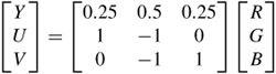 |
Here the colour decorrelation is not as good as ICT, but it has the property that if YUV are losslessly coded, then exact values of the original RGB can be retrieved. This type of transformation is called reversible colour transformation (RCT). RCT may also be used for lossy coding, but since ICT has a better decorrelation property than RCT, use of RCT can reduce the overall compression efficiency.
It is worth mentioning that in compression of colour images, colour fidelity may be traded for that of luminance. In the JPEG standard this is done by subsampling the chrominance components Cb and Cr, or U and V, like the 4:2:2 and 4:2:0 image formats. In JPEG2000, image format is always 4:4:4, and the colour subsampling is done by the wavelet transform of the core encoder. For example, in coding of a 4:4:4 image format, if the highest LH, HL and HH bands of Cb and Cr chrominance components are set to zero, it has the same effect as coding of a 4:2:0 image format.
5.4.2 Core encoder
Each transformed colour component of YCbCr/YUV is coded by the core encoder. As in the JPEG encoder, the main elements of the core encoder are: transformation, quantisation and entropy coding. Thus a more detailed block diagram of JPEG2000 is given by Figure 5.11.
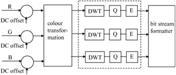
Figure 5.11: The encoding elements of JPEG2000
In the following sections these elements and their roles in image compression are presented.
5.4.2.1 Discrete wavelet transform
In JPEG2000, transformation of pixels that in the JPEG standard used DCT has been replaced by the discrete wavelet transform (DWT). This has been chosen to fulfil some of the requirements set forth by the JPEG2000 committee. For example:
-
Multiresolution image representation is an inherent property of the wavelet transform. This also provides simple SNR and spatial scalability, without sacrificing compression efficiency.
-
Since the wavelet transform is a class of lapped orthogonal transforms then, even for small tile sizes, it does not create blocking artefacts.
-
For larger dimension images, the number of subband decomposition levels can be increased. Hence, by exploiting a larger area of pixel intercorrelation a higher compression gain can be achieved. Thus for images coded at low bit rates, DWT is expected to produce better compression gain than the DCT which only exploits correction with 8 × 8 pixels.
-
DWT with integer coefficients, such as the (5,3) tap wavelet filters, can be used for lossless coding. Note that in DCT, since the cosine elements of the transformation matrix are approximated, lossless coding is not then possible.
The JPEG2000 standard recommends two types of filter bank for lossy and lossless coding. The default irreversible transform used in the lossy compression is the Daubechies 9-tap/7-tap filter [12]. For the reversible transform, with a requirement for lossless compression, it is LeGall and Tabatabai's 5-tap/3-tap filters as they have integer coefficients [13]. Table 5.5 shows the normalised coefficients (rounded to six decimal points) of the lowpass and highpass analysis filters H0(z)/H1(z) of the 9/7 and 5/3 filters. Those of the synthesis G0 (z) and G1(z) filters can be derived from the usual method of G0(z) = H1 (-z) and G1 (z) = -H0(-z).
| Coefficients | Lossy compression (9/7) | Lossless compression (5/3) | ||
|---|---|---|---|---|
| lowpass H0(z) | highpass H1(z) | lowpass H0(z) | highpass H1(z) | |
| 0 | +0.602949 | +1.115087 | 3/4 | 1 |
| ±1 | +0.266864 | -0.591272 | 1/4 | -1/2 |
| ±2 | -0.078223 | -0.057544 | -1/8 | |
| ±3 | -0.016864 | +0.091272 | ||
| ±4 | +0.026729 | |||
Note that to preserve image energy in the pixel and wavelet domains, the integer filter coefficients in lossless compression are normalised for unity gain. Since the lowpass and highpass filter lengths are not equal, these types of filter are called biorthogonal. The lossy 9/7 Daubechies filter pairs [12] are also biorthogonal.
5.4.2.2 Quantisation
After the wavelet transform, all the coefficients are quantised linearly with a dead band zone quantiser (Figure 3.5). The quantiser step size can vary from band to band and since image tiles are coded independently, it can also vary from tile to tile. However, one quantiser step size is allowed per subband of each tile. The choice of the quantiser step size can be driven by the perceptual importance of that band on the human visual system (HVS), similar to the quantisation weighting matrix used in JPEG (Table 5.1), or by other considerations, such as the bit rate budget.
As mentioned in Chapter 4, wavelet coefficients are most efficiently coded when they are quantised by successive approximation, which is the bit plane representation of the quantised coefficients. In this context the quantiser step size in each subband, called the basic quantiser step size, A, is related to the dynamic range of that subband, such that the initial quantiser step size, after several passes, ends up with the basic quantiser step size A. In JPEG2000, the basic quantiser step size for band b, Δb, is represented with a total of two bytes, an 11-bit mantissa μb and a five-bit exponent εb according to the relationship:
| (5.6) |
where Rb is the number of bits representing the nominal dynamic range of subband b. That is ![]() is greater than the magnitude of the largest coefficient in subband b. Values of μb and εb for each subband are explicitly transmitted to the decoder. For lossless coding, used with reversible (5,3) filter banks, μb = 0 and εb = Rb, which results in Δb = 1. On the other hand, the maximum value of Δb is almost twice the dynamic range of the input sample when εb = 0 and μb has its maximum value, which is sufficient for all practical cases of interest.
is greater than the magnitude of the largest coefficient in subband b. Values of μb and εb for each subband are explicitly transmitted to the decoder. For lossless coding, used with reversible (5,3) filter banks, μb = 0 and εb = Rb, which results in Δb = 1. On the other hand, the maximum value of Δb is almost twice the dynamic range of the input sample when εb = 0 and μb has its maximum value, which is sufficient for all practical cases of interest.
5.4.2.3 Entropy coding
The indices of the quantised coefficients in each subband are entropy coded to create the compressed bit stream. In Chapter 4 we introduced three efficient methods of coding these indices, namely: EZW, SPIHT and EBCOT. As mentioned in section 4.7, the JPEG committee chose embedded block coding with optimised truncation (EBCOT), due to its many interesting features that fulfil the JPEG2000 objectives. Details of EBCOT were given in section 4.7, and here we only summarise its principles and show how it is used in the JPEG2000 standard.
In EBCOT, each subband of an image tile is partitioned into small rectangular blocks, called code blocks, and code blocks are encoded independently. The dimensions of the code blocks are specified by the encoder and, although they may be chosen freely, there are some constraints; they must be an integer power of two; the total number of coefficients in a code block cannot exceed 4096 and the height of the code block cannot be less than four. Thus the maximum length of the code block is 1024 coefficients.
The quantiser indices of the wavelet coefficients are bit plane encoded one bit at a time, starting from the most significant bit (MSB) and preceding to the least significant bit (LSB). During this progressive bit plane encoding, if the quantiser index is still zero, that coefficient is called insignificant. Once the first nonzero bit is encoded, the coefficient becomes significant and its sign is encoded. For significant coefficients, all subsequent bits are referred to as refinement bits. Since in the wavelet decomposition the main image energy is concentrated at lower frequency bands, many quantiser indices of the higher frequency bands will be insignificant at the earlier bit planes. Clustering of insignificant coefficients in bit planes creates strong redundancies among the neighbouring coefficients that are exploited by JPEG2000 through a context-based adaptive arithmetic coding.
In JPEG2000, instead of encoding the entire bit plane in one pass, each bit plane is encoded in three subbit plane passes. This is called fractional bit plane encoding, and the passes are known as: significance propagation pass, refinement pass and clean up pass. The reason for this is to be able to truncate the bit stream at the end of each pass to create the near optimum bit stream. Here, the pass that results in the largest reduction in distortion for the smallest increase in bit rate is encoded first.
In the significance propagation pass, the bit of a coefficient in a given bit plane is encoded if and only if, prior to this pass, the coefficient was insignificant and at least one of its eight immediate neighbours was significant. The bit of the coefficient in that bit plane, 0 or 1, is then arithmetically coded with a probability model derived from the context of its eight immediate neighbours. Since neighbouring coefficients are correlated, it is more likely that the coded coefficient becomes significant, resulting in a large reduction in the coding distortion. Hence this pass is the first to be executed in fractional bit plane coding.
In the refinement pass, a coefficient is coded if it was significant in the previous bit plane. Refining the magnitude of a coefficient reduces the distortion moderately. Finally, those coefficients that were not coded in the two previous passes are coded in the clean up pass. These are mainly insignificant coefficients (having eight insignificant immediate neighbours) and are likely to remain insignificant. Hence their contribution in reducing distortions is minimal and is used in the last pass. For more details of coding, refer to EBCOT in section 4.7.
5.4.3 Postprocessing
Once the entire image has been compressed, the bit stream generated by the individual code blocks is postprocessed to facilitate various functionalities of the JPEG2000 standard. This part is similar to the layer formation and bit stream organisation of EBCOT known as tier 2 (see section 4.7).
To form the final bit stream, the bits generated by the three spatially consistent coded blocks (one from each subband at each resolution level) comprise a packet partition location, called a precinct [10]. A collection of packets, one from each precinct, at each resolution level comprises the layer. Figure 5.12 shows the relationship between the packetised bit stream and the units of image, such as the code block, precinct, tile and the image itself.
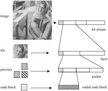
Figure 5.12: Correspondence between the spatial data and bit stream
Here, the smallest unit of compressed data is the coded bits from a code block. Data from three code blocks of a precinct makes a packet, with an appropriate header, addressing the precinct position in the image. Packets are then grouped into the layer and finally form the bit stream, all with their relevant headers to facilitate flexible decoding. Since precincts correspond to spatial locations, a packet could be interpreted as one quality increment for one resolution at one spatial location. Similarly, a layer could be viewed as one quality increment for the entire image. Each layer successively and gradually improves the image quality and resolution, so that the decoder is able to decode the code block contributions contained in the layer, in sequence. Since ordering of packets into the layer and hence into the bit stream can be as desired, various forms of progressive image transmission can be realised.
EAN: 2147483647
Pages: 148