Overview of MSCS
3 4
MSCS is a built-in service of Windows 2000 Advanced Server, Windows 2000 Datacenter Server, and Windows NT 4 Enterprise Edition. MSCS is used to form a server cluster, which, as mentioned earlier, is a group of independent servers working collectively as a single system. The purpose of the cluster is to preserve client access to applications and other resources in the event of a failure or planned outage. If one of the servers in the cluster is unavailable for any reason, the resources and applications move to another node in the cluster.
When we talk about clustered systems, we generally use the term "high availability" rather than "fault tolerant." Traditionally, the term "fault tolerant" refers to a specialized system that offers an extremely high level of redundancy, resilience, and recovery. This type of system normally uses highly specialized software to provide a nearly instantaneous recovery from any single hardware or software failure. Fault-tolerant systems are significantly more expensive than systems without fault tolerance. Clustered systems, which offer high availability, are not as costly as fault-tolerant systems. Clustered systems are generally composed of standard server hardware and a small amount of cluster-aware software in the operating system. As the availability needs of the installation increase, systems can be added to the cluster with relative ease. Though a clustered system does not guarantee continuous operation, it does provide greatly increased availability for most mission-critical applications.
A system running MSCS provides high availability and a number of other benefits. Some of the benefits of running MSCS are described here:
- High availability System resources, such as disk drives and IP addresses, are automatically transferred from a failed server to a surviving server. This is called failover. When an application in the cluster fails, MSCS automatically starts the application on a surviving server, or it disperses the work from the failed server to the remaining nodes. Failover happens quickly, so users experience only a momentary pause in the service.
- Failback When a failed server is repaired and comes back on line, MSCS automatically rebalances the workloads in the cluster. This is called failback.
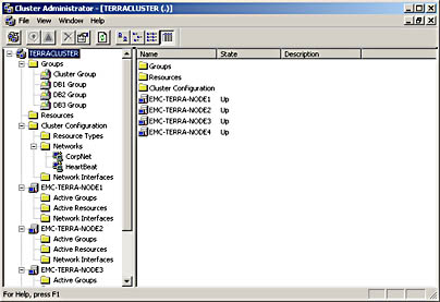
- Manageability The Cluster Administrator software allows you to manage the entire cluster as a single system. You can easily move applications to different servers within the cluster by dragging the cluster objects in Cluster Administrator. You can move data in the same manner. These drag-and-drop operations can be used to manually balance server workloads or to "unload" a server to prepare it for planned downtime and maintenance. Cluster Administrator also allows you to monitor (from anywhere in the network) the status of the cluster, each node, and all the resources available. Figure 12-1 shows an example of the Cluster Administrator window.
- Scalability As the demands of the system increase, MSCS can be reconfigured to support the increase. Nodes can be added to the cluster when the overall load exceeds the capabilities of the cluster.
Basic Concepts
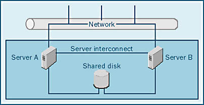
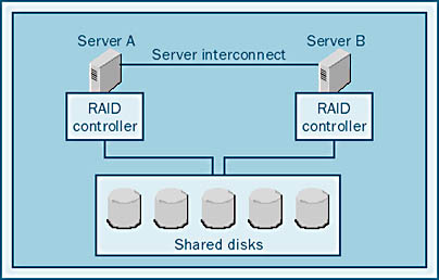
MSCS reduces downtime by providing failover between multiple systems using a server interconnect and a shared disk system, as Figure 12-2 illustrates. The server interconnect can be any high-speed connection, such as an Ethernet network or other networking hardware. The server interconnect acts as a communication channel between the servers, allowing information about the cluster state and configuration to be passed back and forth. The shared disk system allows the database and other data files to be equally accessed by all of the servers in the cluster. This shared disk system can be SCSI, SCSI over Fibre Channel, or other proprietary hardware. The shared disks can be either stand-alone disks or a RAID system. (RAID systems are described in Chapter 5.)
CAUTION
If the shared disk system is not fault tolerant and a disk subsystem fails, MSCS will fail over to another server, but the new server will still use the same failed disk subsystem. Be sure to protect your disk drives by using RAID, because these mechanical devices are the components most likely to fail.
Once a system has been configured as a cluster server, it is transformed from a traditional server into what is called a virtual server. A virtual server looks like a normal server, but the actual physical identity of the system has been abstracted away. Because the computer hardware that makes up this virtual server might change over time, the user does not know which actual server is servicing the application at any given moment. Therefore, the virtual server, not a particular set of hardware, serves user applications.
A virtual server exists on a network and is assigned an IP address used in TCP/IP. This address can switch from one system to another, enabling users to see the virtual server regardless of what hardware it is running on. The IP address will actually migrate from one system to another to maintain a consistent presentation of the virtual server to the outside world. An application directed to a specific address can still access the address if a particular server fails, even though the address then represents a different server. The virtual server keeps the failover operations hidden from the user, so the user can keep working without knowing what's happening "behind the scenes."
Cluster Components
Several components are required to create a cluster: cluster management software, a server interconnect, and a shared disk system. These components must be configured in conjunction with cluster-aware applications to create a cluster. In this section, you'll learn about the various components and how they work together to create the cluster. In the section "SQL Server Cluster Configuration" later in this chapter, you'll learn how to configure a SQL Server cluster.
MSCS Cluster Management Software
The cluster management software is actually a set of software tools used to maintain, configure, and operate the cluster. It consists of the following subcomponents, which work together to keep the cluster functioning and to perform failover if necessary:
- Node Manager Maintains cluster membership and sends out "heartbeats" to members (nodes) of the cluster. (Heartbeats are simply "I am alive" messages sent out periodically.) If a node's heartbeats stop, another node will think that this node is no longer functioning and will take steps to take over its functions. Node Manager is one of the most critical pieces of the cluster because it monitors the state of the cluster and its members and determines what actions should be taken.
- Configuration Database Manager Maintains the cluster configuration database. This database keeps track of all of the components of the cluster, including the abstract logical elements (such as virtual servers) and physical elements (such as the shared disks). This database is similar to the Windows NT/Windows 2000 registry.
- Resource Manager/Failover Manager Starts and stops MSCS. Resource Manager/Failover Manager receives information (such as the loss of a node, the addition of a node, and so on) from Resource Monitor and Node Manager.
- Event Processor Initializes the cluster and routes event information among components of the cluster. Event Processor also initiates cluster expansion by directing Node Manager to add a node.
- Communications Manager Manages communication between the nodes in the cluster. All nodes in the cluster must communicate with each other constantly to function properly. If the nodes did not have this contact, cluster state information would be lost, and the cluster would not function.
- Global Update Manager Communicates cluster state information (including information about the addition of a node to a cluster, the removal of a node, and so on) to all nodes in a cluster.
- Resource Monitor Monitors the condition of the various resources in the cluster and provides statistical data. This information can be used to determine whether any failover action needs to be taken in the cluster.
- Time Service Ensures that all nodes in the cluster report the same system time. If Time Service were not present, events might seem to occur in the wrong sequence, resulting in bad decisions. For example, if one node that thought it was 2 P.M. and contained an old copy of a file and another node that thought it was 10 A.M. and contained a newer version of that file, the cluster would erroneously determine that the file on the first system was the most recent.
Server Interconnect
The server interconnect is simply the connection between the nodes in the cluster. Because the nodes in the cluster need to be in constant communication (via Time Service, Node Manager, and so on), it is important to maintain this link. So the server interconnect must be a reliable communication channel between these systems.
In many cases, the server interconnect will be an Ethernet network running TCP/IP or NetBIOS. This setup is adequate, but you might also want to use a proprietary, high-speed interconnect that is much faster than Ethernet. These interconnects are commercially available from many hardware vendors, and some provide communications services as well as shared-disk services. A complete list of approved server interconnect devices is available from the hardware compatibility list on the Microsoft Web site at http://www.microsoft.com/hcl/.
Shared Disk System
Another key component of cluster creation is the shared disk system. If multiple computer systems can access the same disk system, another node can take over if the primary node fails. This shared disk system must allow multiple computer systems to have equal access to the same disks—in other words, each of the computers must be able to access all of the disks. In the current version of MSCS, only one system can access the disk at a time, but future versions will allow multiple systems to access the data simultaneously.
Several types of shared disk systems are available, and new disk technology is always being developed. The SCSI disk subsystem has always supported multiple initiators. With multiple initiators, you can have multiple SCSI controllers on the same SCSI bus, which makes SCSI ideal for clustering. In fact, SCSI systems were the first disk subsystems to be used for clustering.
More recent disk technologies, such as Fibre Channel and some proprietary solutions, are designed to support clustering. Fibre Channel systems allow disks to connect over a long distance from the computer system. Most Fibre Channel systems support multiple controllers on the same Fibre Channel loop. Some RAID controllers are designed or have been modified to support clustering. Without modification or configuration changes, most disk controllers will not support clustering.
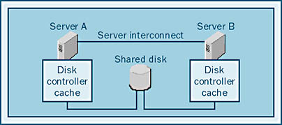
Controller caches that allow writes to be cached in memory are also an issue with clustering when the cache is located on the controller itself, as shown in Figure 12-3. In this case, each node contains its own cache, and we say that the cache is "in front of" the disk sharing because two caches share the same disk drives. If each controller has a cache and a cache is located on a system that fails, the data in the cache might be lost. For this reason, when you use internal controller caches in a cluster configuration, they should be set as read-only. (Under some conditions, this setting might reduce the performance of some systems.)
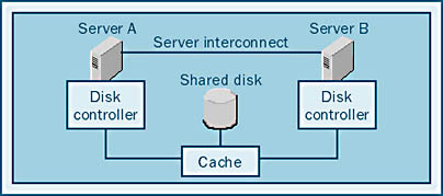
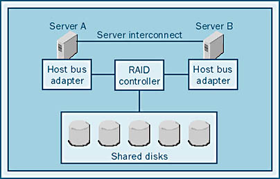
Other solutions to the shared-disk problem involve RAID striping and caching in the disk system itself. In this configuration, the cache is shared by all nodes, and we say that the cache is "behind" the sharing, as shown in Figure 12-4. Here, the striping mechanisms and the cache are viewed identically by all of the controllers in the system, and both read caching and write caching are safe.
Newer SCSI and Fibre Channel disk subsystems allow the RAID controller to be in the disk enclosure, rather than in the computer system. These systems offer good performance and fault tolerance. In fact, many RAID systems of this type offer fully redundant controllers and caches. Many of the newer RAID systems use this type of architecture. Let's look at some disk subsystems in detail.
I/O Subsystems As mentioned, various types of I/O subsystems support clustering. The three main types of I/O subsystems are as follows:
- SCSI JBOD This is a SCSI system with multiple initiators (controllers) on a SCSI bus that address JBOD (short for "just a bunch of disks"). In this setup, the disks are individually addressed and must be either configured into a stripe using Windows 2000 striping or addressed individually. This subsystem is not recommended.
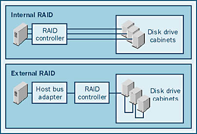
- Internal RAID A RAID controller is used in each server. The disadvantage of this subsystem is that the RAID logic is on the board that goes in the server and thus the controller caches must be disabled.
- External RAID The RAID controller is shared by the systems in the cluster. The cache and the RAID logic are in the disk enclosure, and a simple host bus adapter (HBA) is used to communicate with the external controller.
The next two sections address only the two RAID solutions. The SCSI JBOD solution is not advisable unless the cluster is small and cost is a major issue.
Internal RAID Internal RAID controllers are designed such that the hardware that controls the RAID processing and the cache reside in the host system. With internal RAID, the shared disk system is shared behind the RAID striping, as shown in Figure 12-5.
Because the cache is located on the controller, which is not shared, any data in the cache when the system fails will not be accessible. This is a big problem when a relational database management system (RDBMS) is involved. When SQL Server writes data to disk, that data has been recorded in the transaction log as having been written. When SQL Server attempts to recover from a system failure, these data blocks will not be recovered because SQL Server thinks that they have already been written to disk. In the event of a failure in this type of configuration, the database will become corrupted.
Therefore, vendors certify their caching RAID controllers for use in a cluster by disabling the cache (or at least the write cache). If the cache has been disabled, SQL Server will not be signaled that a write operation has been completed until the data has actually been written to disk.
NOTE
SQL Server performs all writes to disk in a nonbuffered, noncached mode. Regardless of how much file system cache is available, SQL Server will not use it. SQL Server completely bypasses the file system cache, as do most RDBMS products.
In certain situations, using the controller cache can provide a great performance benefit. This is particularly true when you are using a RAID 10 or RAID 5 configuration because writes incur additional overhead with these RAID levels. To use a controller write cache in a cluster configuration, you must use an external RAID system so that the cache is shared and data is not lost in a failover.
External RAID In an external RAID system, the RAID hardware is outside the host system, as shown in Figure 12-6. Each server contains an HBA whose job is to get as many I/O requests as possible out to the RAID system as quickly as possible. The RAID system determines where the data actually resides.
An external RAID subsystem is sometimes referred to as "RAID in the cabinet" or "RAID in the box" because RAID striping takes place inside the disk cabinet. The external RAID subsystem has many advantages. Not only is it an ideal solution for MSCS, but it's also a great solution overall. The advantages of the RAID-in-the-cabinet approach include the following:
- Allows easier cabling Using internal RAID, you need multiple cables—one for each disk cabinet—coming from the RAID controller. With external RAID, you run one cable from the HBA to the RAID controller and then you run cables from the controller to form a daisy chain connecting each of the disk cabinets, as illustrated in Figure 12-7. External RAID makes it easy to connect hundreds of drives.
- Allows RAID redundancy Many of the external RAID solutions allow one storage controller to communicate with both a primary and a secondary RAID controller, allowing full redundancy and failover.
- Allows caching in a cluster You can configure a caching RAID solution much more easily using external RAID. If you use external RAID, you can enable both caching and fault tolerance without having to worry about cache consistency between controllers (because there is only one cache and one controller). In fact, using the write cache is safe if you use external RAID controllers. You still run some risks if you are caching RDBMS data, but you reduce those risks if you use external RAID controllers. Be sure that your external RAID system vendor supports mirroring of caches. Mirrored caches provide fault tolerance to the cache memory in case a memory chip fails.
- Supports more disk drives In the case of large or high-performance systems, it is sometimes necessary to configure a large number of drives. The need for a large number of drives was illustrated in Chapter 6, where you learned how to size the system; you'll see it again in Chapter 36, when you learn about common performance problems. External RAID devices let you connect hundreds of disks to a single HBA. Internal RAID systems are limited to a few dozen drives per controller, as are SCSI systems.
Of the disk subsystems available today that support clustering, external RAID cabinets are preferable for large clusters. Of course, cost might be a consideration, and some clusters are too small to justify using external RAID. But, in the long run, an external RAID solution will provide the best performance, reliability, and manageability for your cluster.
Cluster Application Types
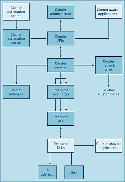
Applications that run on systems running MSCS fall into one of four categories:
- Cluster-unaware applications Applications of this type do not have any interaction with MSCS. Although they might run adequately under normal conditions, they might not perform well if a failure occurs, forcing them to fail over to another node.
- Cluster-aware applications These applications are aware of MSCS. They take advantage of MSCS for performance and scalability. They react well to cluster events and generally need little or no attention after a component fails and the failover occurs. SQL Server 2000 is an example of a cluster-aware application.
- Cluster management applications Applications of this type are used to monitor and manage the MSCS environment.
- Custom resource types These applications provide customized cluster management resources for applications, services, and devices.
Figure 12-8 illustrates the application types and their interaction with MSCS.
MSCS Modes
You can run SQL Server 2000 cluster support and MSCS in different modes. In active/passive mode, one server remains in standby mode, ready to take over in the event of a system failure on the primary server. In active/active mode, each server runs a different SQL Server database. In the event of a failure on either of the servers, the other server takes over. In this case, one server ends up running two databases. In this section, we'll examine the advantages and the disadvantages of using each of these modes.
Active/Passive Clusters
An active/passive cluster uses the primary node to run the SQL Server application, and the cluster uses the server in the secondary node as a backup, or standby, server, as illustrated in Figure 12-9.
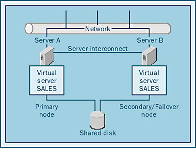
In this configuration, one server is essentially unused. This server might go for months without ever being called into action. In fact, in many cases, the backup server is never used. Because the secondary server is not being used, it might be seen as a costly piece of equipment that is sitting idle. Because this server is not available to perform other functions, other equipment might have to be purchased in order to serve users, making the active/passive mode potentially expensive.
Although the active/passive mode can be expensive, it does have advantages. With the active/passive configuration, if the primary node fails, all resources of the secondary node are available to take over the primary node's activity. This reliability can be important if you're running mission-critical applications that require a specific throughput or response time. If this is your situation, active/passive mode is probably the right choice for you.
It is highly recommended that the secondary node and the primary node have identical hardware (that is, the same amount of RAM, the same type and number of CPUs, and so on). If the two nodes have identical hardware, you can be certain that the secondary system will perform at nearly the same rate as the primary system. Otherwise, you might experience a performance loss in the event of a failover.
Active/Active Clusters
In an active/active cluster, each server can run applications while serving as a secondary server for another node, as illustrated in Figure 12-10.
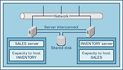
Each of the two servers acts both as a primary node for some applications and as a secondary node for the other server's applications. This is a more cost-effective configuration because no equipment is sitting idle, waiting for another system to fail. Both systems are actively serving users. In addition, a single passive node can act as a secondary node for several primary nodes.
One disadvantage of the active/active configuration is that, in the event of a failure, the performance of the surviving node will be significantly reduced because of the increased load on the secondary node. The surviving node now has to run not only the applications it was running originally but also the applications from the primary node. In some cases, performance loss is unacceptable, and the active/passive configuration is required.
EAN: N/A
Pages: 264