IO Subsystem Concepts
3 4
Hardware RAID controllers provide not only the basic RAID functionality but also additional features. The most common of these hardware RAID features is the controller cache. In this section, you will learn about the controller cache, disk drive caches, and the difference between internal and external RAID. In addition, you will learn about the latest in I/O technology, the Storage Area Network. This section also covers some miscellaneous issues concerning RAID controllers and disk drives, as well as bandwidth issues.
Caching Controllers
To improve I/O performance, many vendors offer controllers with caches. A controller cache is RAM that resides on the disk controller. This cache serves two purposes:
- Write caching Because there is memory on the controller, it is possible for the controller to tell the operating system (and subsequently SQL Server) that the I/O operation has been completed as soon as it has been written to the cache, thus greatly increasing write performance.
- Read-ahead caching Another use of the controller cache is to read data in addition to the data that was requested. This is in anticipation of that additional data's being requested soon. If it is, the response time will be dramatically shorter.
As you will see later in this chapter, write performance can be crucial, especially if you use RAID level 5. In most cases, the controller cache is of great benefit. There are, however, a couple of things to watch for:
- Don't use write caching without a battery backup. Most caching controllers include a battery or offer one as an option. This battery retains data in the cache in the event of a power failure. Without this battery, the data in the cache would be lost, and the database might become corrupted.
- In rare situations where the RAID array is run near capacity, write caching can actually hurt read performance. This is because of the priority within the controller that writes are given in order to empty the cache.
Controller caches can enhance the performance of your I/O subsystem under certain conditions. By understanding the various RAID levels and their performance characteristics, you will be better able to configure these controllers to perform optimally for your particular application and requirements.
Disk Drive Caches
Most disk drives also contain a memory cache. This cache is smaller than the controller cache. It can hold a few requests at a time, allowing the disk drive itself to do elevator sorting. However, because the cache is so small (usually a few kilobytes), it cannot be used for large read-aheads or to cache large amounts of data. Many RAID controller vendors and SCSI controller vendors do not allow you to modify the state of this cache. However, some RAID manufacturers do allow you to turn this cache on or off.
Internal vs. External RAID
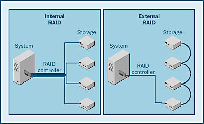
There are two basic types of RAID systems: internal and external. These terms refer to where, in the configuration, the RAID logic lies. With most systems, the RAID logic resides on the controller, which resides in the chassis that houses the computer system. This is referred to as an internal RAID system. In an external RAID system, the RAID logic resides in the storage unit or units that house the disk drives. A representation of these types of systems is shown in Figure 5-5. Each type of system has its own properties and characteristics. However, the differences between internal and external RAID are not really central to this chapter. These two types of controllers are presented only for completeness.
In the next section, you will learn about the various RAID levels. These levels further distinguish RAID controllers.
Storage Area Networks
One of the newest technologies on the market is the Storage Area Network (SAN). A SAN is basically a large external RAID system that shares out the storage among several systems. This is why the term "network" is used in the name. A SAN allows you to consolidate storage and reduce costs while managing and supporting the system from a central location.
The concept of a SAN is fairly straightforward. An external RAID system connects a host bus adapter (HBA) directly to a RAID subsystem. As Figure 5-6 shows, a SAN connects multiple HBAs through a switch to at least one external RAID system. With this setup, all of the systems on the SAN can access the RAID subsystem.

Figure 5-6. A SAN system.
When this book was written, it was impossible for multiple systems to share a logical disk drive within the SAN. The SAN software segmented the storage, and logical drives were allocated to specific systems. However, a SAN can offer several benefits:
- Clustering The SAN is easily clustered because it already is an external RAID controller. The servers can share all of the RAID intelligence.
- Storage consolidation Having one central storage facility reduces storage maintenance problems.
- Reduction of wasted space Rather than reserving an extra disk drive for each system, you can put the extra space to productive use by many systems.
- Fault tolerance All of the systems accessing the SAN can share online spares, which can immediately replace a failed disk drive.
Controller and Bus Bandwidth Issues
In addition to considering disk drive limitations, you should consider bandwidth limitations of the I/O bus (usually SCSI or Fibre Channel). Because buses run at a specified clock speed and have a certain data width (32 bits, 64 bits, and so on), the maximum throughput is fixed. Your requirements can meet or exceed the bandwidth of the controller, the PCI bus, or the controller I/O bus. You can avoid this by spreading your controllers among several PCI buses in your system. Most new computer systems contain three or more PCI buses.
High-End I/O Subsystems
Companies that require 99.99 percent or more system uptime and maximum performance will often turn to vendors like EMC. These vendors offer sophisticated I/O subsystems that include gigabytes of cache capacity and multiple data paths (channels) from the computer system to the disk drive. These multiple channels guarantee a level of redundancy. If a single component in the system were to fail (including an I/O channel, a controller, or the cache), the subsystem would continue to function. If sized carefully, these subsystems can offer the highest level of performance and reliability.
Elevator Sorting
Elevator sorting is a method of making random I/O operations more efficient. When random I/O requests are issued to disks, the heads must randomly move in and out of the disk drive. This random operation causes latencies, as was described earlier. Many RAID controllers support elevator sorting to make random seeks more efficient. If elevator sorting is supported and multiple I/O operations are queued up on the controller, the operations can be sorted to reduce head movement. The advantages of elevator sorting resemble those of using an elevator to move people from one floor to another.
Imagine that an elevator serviced floors in the order in which the people on the elevator pushed the buttons. The elevator might pass floors where it could more efficiently let people on and off. A real elevator is more efficient because it stops on floors where it is needed. Elevator sorting algorithms do the same thing. If more than one I/O operation is in the queue, the controller will take the most efficient path to empty the queue, as Figure 5-7 illustrates.
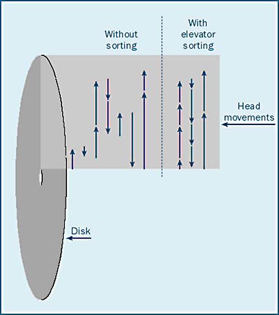
As you can see, elevator sorting can make disk seeking more efficient. Overall seek times are reduced—perhaps at the expense of some individual seek times. However, in order for elevator sorting to occur, you must have several or even many I/O operations outstanding on the controller or disk drive where the sorting is to occur. This situation can often arise when the I/O subsystem is overloaded. In many cases, an optimally running disk drive has only one or two I/O operations outstanding, making elevator sorting a moot point.
Disk Reliability
Disks are one of the few components in a computer system that is at least partly mechanical. The disk drive spins at a high rate and operates at a high temperature. Components include several motors and bearings that eventually wear out. Included in the disk drive specifications is duration for mean time between failures (MTBF). The figure for duration indicates how long a disk is expected to last on average. However, this number is only an average. Some disk drives last longer than others that have the same MTBF estimate. A typical modern disk drive might have an MTBF of 1,000,000 hours, or 114 years. This is a long time; however, some disks with that rating will last much longer, and some will fail early on. The point is that disks have mechanical components, and they are thus subject to wear and tear and eventual failure.
EAN: N/A
Pages: 264