Practical Applications: Label Distribution
|
| < Day Day Up > |
|
Hundreds of pages worth of forum comments have been written about label distribution methods, including OSPF-TE and LDP.
The LDP protocol is standardized as detailed in RFC 3036. To obtain detailed vendor explanations and commands, contact Cisco, Juniper, and Riverstone.
In this section, we take a look at how to establish the LDP protocol on a Riverstone router and how to show LDP status. For other vendors, see the related links at the end of the chapter.
| Note | With some vendors, RSVP and LDP protocols may not be enabled on the same interfaces. |
Configuration Steps
The configuration of LDP will vary in accordance with how a router is configured. If interfaces have already been created with routing protocols, and MPLS is running, the next step is configuring the LDP protocol. The process of doing so is explained in this section.
If you must configure LDP on an interface that is yet to be created, four basic steps are involved. They are outlined here and described in the following sections:
-
Create and enable the interface.
-
Create OSPF on the interfaces.
-
Create and enable MPLS on the new interfaces.
-
Create and enable LDP.
Enabling the Label Distribution Protocol
LDP, works very differently from RSVP-TE. In the case of LDP, simply enabling the protocol on the required interfaces will allow the routers to discover directly connected label distribution peers via multicast UDP packets and, subsequently, to establish a peering relationship over TCP.
Each router will create and distribute a label binding to an FEC for each loopback interface that is defined in the router. Each physical interface that is expected to interpret and function in an LDP environment must be added to it. To enable LDP capabilities on an interface, simply add it to the LDP process.
rs(config)# ldp add interface <name|all>
To start the LDP process on the router:
rs(config)# ldp start
The loopback interface is added automatically when all interfaces are added to LDP as a group. This interface is required to establish remote LDP peering sessions, and if the all option is not used to add the interfaces to LDP, the lo0 interface must be explicitly added.[1]
Configuring New Interfaces with Show Commands
We use Figure 2.9 to show the configuration of LDP from LER1 (far left) to LSR 1 and LSR 2. The four basic steps that were detailed above are explained along with the related show commands.
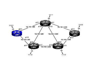
Figure 2.9: Full Network Diagram
IGP, MPLS, and LDP are only enabled on the core-facing interfaces. This network and the associated configuration form the basis for show commands that follow.
Create and Enable the Interface
The interface is created by following the commands shown in Figures 2.10–2.12. In Figure 2.10, the interface with the IP address 192.168.1.2/30 is created.
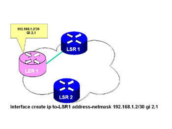
Figure 2.10: Creating the Interface
Figure 2.11 shows the creation of the second interface on router LER1 for the 192.168.1.6/30 address. In Figure 2.12, the interface LoO with an address of 2.2.2.1 is created.
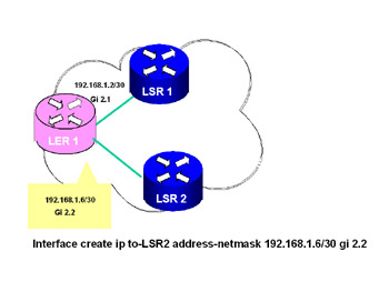
Figure 2.11: Detailed View of LER1 Interface gi 2.2
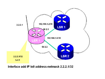
Figure 2.12: Detailed View of LER1 Local Interface Lo 0Create OSPF on Interfaces
Figures 2.13 and 2.14 show how OSPF is created in the routers. In Figure 2.13, the router ID is set; in Figure 2.14, OSPF is added to the interfaces and OSPF is started.
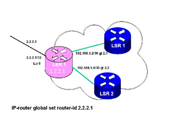
Figure 2.13: LER1 Global Routing
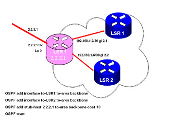
Figure 2.14: LER1 Enable OSPF
Create and Enable MPLS on New Interface
Figure 2.15 shows how MPLS is added to the interfaces LSR1 and LSR2. After MPLS is added, it must be started by a command line.
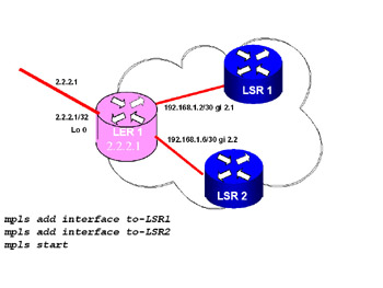
Figure 2.15: MPLS Added to Interface
Create and Enable LDP
After MPLS is added, LDP must be added to each MPLS interface. Figure 2.16 shows how LDP is added to the interfaces and then started.
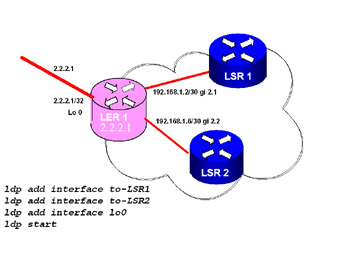
Figure 2.16: LDP Started
LDP Session Information
High-level session information for each peer is shown in Table 2.6.
| Possible Session States | Description |
|---|---|
| Nonexistent | No session exists |
| Connecting | TCP connection is in progress |
| Initialized | TCP connection established |
| OpenSent | Initialization or keepalive messages being transmitted |
| OpenRec | Keepalive message being transmitted |
| Operational | Session established |
| Closing | Closing session |
RS# ldp show sessions all
-
Address of peer
-
State of the session
-
TCP connection state (closed, opening, open)
-
Time before session expires without a keepalive
-
Number of labels sent and received and received labels filtered
The LDP show session command is very powerful with several command extensions. Figure 2.17 is a graphic of the network represented by the show LDP session command.
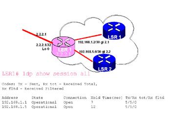
Figure 2.17: Show LDP Sessions
Other Show Commands
LDP show sessions all verbose
A more detailed view of the session information is available by coding the verbose option. The following additional information is available with this option:
-
Session ID (comprising both LDP identifiers)
-
Timer values
-
Local and remote physical interfaces
-
A list of LDP-enabled interfaces on the remote peer
LDP Neighbor Information
Detailed neighbor information for each peer:
RS# ldp show neighbor verbose
-
Address where neighbor was discovered and interface used to reach neighbor
-
Label space ID indicating the LDP identifier and label space the label was issued from, :0 being from the global space
-
Time before session expires without a keepalive
-
Transport address used for establishing the session
Figure 2.18 is a graphic representation of the text command show LDP neighbor.
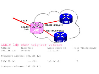
Figure 2.18: Show LDP Neighbor
LDP Statistical Information
Statistical information about the LDP protocol is broken into two horizontal planes, each with a cumulative and a 5-second representation. The tables are self-explanatory. One thing to note: If the statistics are cleared, all the cumulative information is lost, obviously. So when you’re reviewing the statistics following a clear, the “Event Type - Sessions Opened” field may be zero even though there are open sessions. Don’t let this field mislead you into thinking no sessions are formed. The session display command is the authority on session-related information.
RS# ldp show statistics
LDP Interface Information
A detailed view of the LDP interfaces indicates the following for each LDP enabled interface:
RS# ldp show interface all verbose
-
Label space indicating the LDP identifier and label space the label was issued from, :0 being from the global space
-
The number of neighbor sessions that exist on this interface
-
Timer information
-
Label management: retention and distribution
[1]Provided by Riverstone.
|
| < Day Day Up > |
|
EAN: 2147483647
Pages: 138