3. Periodic Broadcast Techniques
3. Periodic Broadcast Techniques
Periodic Broadcast is a highly scalable solution for streaming popular videos. In this environment, a video is segmented into several segments, each repeatedly broadcast on a dedicated channel. A client receives a video by tuning to one or more appropriate channels at a time to download the data. The communication protocol ensures that the broadcast of the next video segment is available to the client before the playback of the current segment runs out. Obviously, this scheme is highly scalable. The system can serve a very large community of users with minimal server bandwidth. In fact, the bandwidth requirement is independent of the number of users the system is designed to support. A limitation of this approach is its non-zero service delay. Since each client cannot begin the playback until the next occurrence of the first segment, its broadcast period determines the worst service latency. Many periodic broadcast techniques have been designed to keep this delay, or the size of the first segment, as small as possible to provide near-on-demand services. These techniques can be classified into two major categories. The first group, called Server-Oriented Approach, includes techniques that reduce service latency by increasing server bandwidth. Methods in the second category, called Client-Oriented Approach, improve latency by requiring more client bandwidth. We discuss these two approaches in this section.
To facilitate the following discussion, we assume a video v of L seconds long. A portion of the server bandwidth, B Mbits/sec, is allocated to v. This dedicated bandwidth is organized into K logical channels by time multiplexing. In other words, we repeatedly broadcast the data segments of v on K channels. The playback rate of v is b Mbits/sec.
3.1 Server-Oriented Approach: Increasing Server Bandwidth
We first focus on techniques that allow the users to reduce service latency by increasing only server bandwidth. The rationale for this approach is that server bandwidth, shared by a large community of users, contributes little to the overall cost of the VOD environment. Researchers in this camp argue that this solution is much less expensive than the Client-Oriented Approach which demands each user to equip with substantial client bandwidth, e.g., using a T1 line instead of DSL or a cable modem.
3.1.1 Staggered Broadcasting
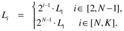
Staggered Broadcasting [8][9] is the earliest and simplest video broadcast technique. This scheme staggers the starting times for the video v evenly across K channels. In other words, if the first channel starts broadcasting video v at the playback rate b at time to, the second channel starts broadcasting the same video at time t0 + L/K, the third channel at time t0 + 2*L/K, and so on. The difference in the starting times, L/K, is called the phase offset. Since a new stream of video v is started every phase offset, it is the longest time any client needs to wait for this video.
Another way to implement the Staggered Broadcasting scheme is as follows. Video v can be fragmented into K segments (S1, S2, S3, .., SK) of equal size, each of length L/K. Each channel Ci,1≤i≤K, repeatedly broadcasts segment Si at the playback rate b. A client requesting video v tunes to channel C1 and waits for the beginning of segment S1. After downloading segment S1, the client switches to channel C2 to download S2 immediately. This process is repeated for the subsequent data segments until segment SK is downloaded from channel Ck.
The advantage of Staggered Broadcasting is that clients download data at the playback rate. They do not need extra storage space to cache the incoming data. This simple scheme, however, scales only linearly with increases to the server bandwidth. Indeed, if one wants to cut the client waiting time by half, one has to double the number of channels allocated to the video. This solution is very demanding on server bandwidth. In the following, we present more efficient techniques that can reduce service latency exponentially with increases in server bandwidth.
3.1.2 Skyscraper Broadcasting
In Skyscraper Broadcasting [18], the server bandwidth of B Mbit/sec is divided into ![]() logical channels of bandwidth b. Each video is fragmented into K data segments. The size of segment Sn is determined using the following recursive function:
logical channels of bandwidth b. Each video is fragmented into K data segments. The size of segment Sn is determined using the following recursive function:
| (31.1) | 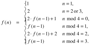 |
Formula (31.1) expresses the size of each data segment in term of the size of the first segment. Expanding this formula gives us the following series referred to as the broadcast series:
[1, 2, 2, 5, 5, 12, 12, 25, 25, …]
That is, if the size of the first data segment is D1, the size of the second and third segments are 2 D1, the fourth and fifth are 5 D1, sixth and seventh are 12 D1, and so forth. This scheme limits the size of the biggest segments to W units or W D1. These segments stack up to a skyscraper, thus the name Skyscraper Broadcasting. W is called the width of the skyscraper.
Skyscraper Broadcasting repeatedly broadcasts each segment on its dedicated channel at the playback rate b. Adjacent segments having the same size form an odd or even group depending on whether their sizes are odd or even, respectively. Thus, the first segment is an odd group by itself; the second and third segments form an even group; the fourth and fifth form an odd group; the sixth and seventh form an even group; and so on. To download the video, each client employs two concurrent threads - an Odd Loader and an Even Loader. They download the odd groups and the even groups, respectively. When a loader reaches the first W-segment, the client uses only this loader to download the remaining W-segments sequentially to minimize the requirement on client buffer space.
Figure 31.4 gives an example of the Skyscraper Broadcasting scheme, where three clients x, y, and z requested the video v just before time slots 5, 10, and 11, respectively. The segments downloaded by each of the three clients are filled with a distinct texture. Let us focus on Client x whose segments are black. Its Odd Loader and Even Loader start downloading the first and second segments, respectively, at the beginning of the fifth time slot. When the second segment is exhausted, the Even Loader switches to download the third segment on Channel 3. Similarly, when the first segment is exhausted, the Odd Loader turns to download first the fourth and then the fifth segments. After the Even Loader has finished downloading the third segment on Channel 3, this loader tunes into Channel 6 to wait for the next occurrence of segment 6 at the beginning of time slot 13. If W is set to 12 in this example, this client will continue to use the Even Loader to download the remaining W-segments. The playback timing of the downloaded segments is illustrated at the bottom of Figure 31.4. We note that each segment is available for download before it is required for the playback.
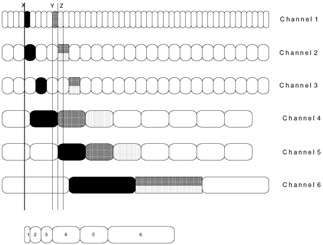
Figure 31.4: Skyscraper downloading scheme.
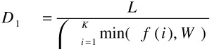
The worst waiting time experienced by any client, which is also the size of the first segment D1, is given by the following formula:
The major advantage of this approach is the fixed requirement on client bandwidth regardless of the desired service latency. To achieve better service latency, one needs only add server bandwidth. This additional cost is usually negligible because the access latency can be reduced at an exponential rate; and server resources are shared by a very large user community. In practice, it is difficult to provide near-on-demand services using Staggered Broadcasting. Skyscraper technique addresses this problem efficiently. As an example, using 10 channels for a 120-minute video, Staggered Broadcasting has a maximum waiting time of 12 minutes while it is less than one minute for Skyscraper Broadcasting. Adding only a few more channels can further reduce this waiting time.
3.1.3 Client-Centric Approach
The Client-Centric Approach (CCA) [16] is another periodic broadcast technique that allows one to improve service delay by adding only server resources once the client capability has been determined. As in the Skyscraper technique CCA divides server bandwidth into K logical channels; each repeatedly broadcasts a distinct video segment. The fragmentation function is given in Formula 31.2, where the parameter c denotes the maximum number of channels each client can tune into at one time to download simultaneously c segments:
| (31.2) | 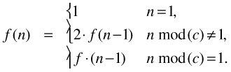 |
CCA can be viewed as a generalization of the Skyscraper technique in that each transmission group can have more than two segments, and the number of data loaders is not limited to two as in Skyscraper Broadcasting. CCA enables applications to exploit the available client bandwidth. This approach, however, is not the same as the Client-Oriented Approach presented in Section 3.2, which, given a fixed client bandwidth, cannot improve the service delay by adding only server resources.
Similar to Skyscraper Broadcasting, CCA also limits the sizes of larger data fragments to W. At the client end, the reception of the video is done in terms of transmission groups. The video segments are grouped into g transmission groups where g = | K/c⌋. Therefore, each group has c segments except for the last group. To receive the video, a client uses c loaders; each can download data at the playback rate b. When a loader Li finishes downloading segment Si in groupj, this loader switches to download segment Si+c in groupj+1. Since segments in the same group (of different sizes) are downloaded at the same time, continuity within the same group is guaranteed. Furthermore, since the size of the last segment in groupj is always the same size as the first segment of the next groupj+1, continuity across group boundaries is also guaranteed. Comparing to the Skyscraper scheme, CCA uses extra client bandwidth to further reduce the access latency. For L=120 minutes (video length), K=10 channels, and c=3 loaders, CCA cut the access latency by half.
3.1.4 Striping Broadcasting
Striping Broadcasting [26] employs a 2D data fragmentation scheme as follows. Let N be the index of the first W-segment. The size of each segment i, denoted by Li, is determined using the following equation:
That is, the size of the first N-1 segments increases geometrically, while the sizes of the other segments (i.e., W-segments) are kept the same. Each of the W-segments is further divided into two equally sized fragments called stripes. Compared to Skyscraper technique, Striping Broadcasting employs a faster segment-size progression. This results in a smaller first segment, and therefore better service latency. Since the size of all segments must be equal to the size of the entire video, we can compute the worst access delay as follows:
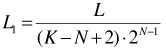
To deliver a video, the server periodically broadcasts each of the first N-1 segments, at the playback rate, on its own channel. Each stripe of the W-segments is also periodically broadcast at half the playback rate. To allow the client to download the W-segments as late as possible to save buffer space, phase offsets are employed in the broadcast. Let Di denote the phase offset for segment i where 1 ≤ i < N; and Di1 and Di2 represent the phase offsets for the first and second stripes, respectively, of segment i where N ≤ i ≤ K. The phase offsets are calculated as follows:
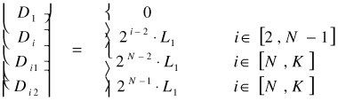
A broadcast example using the non-uniform phase delay is shown in Figure 31.5. The server broadcasts an index at the beginning of each occurrence of the first segment to inform the client when to download the remaining segments.
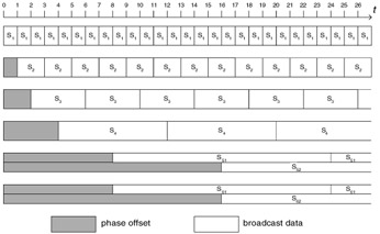
Figure 31.5: Broadcast schedule when N=5 and K=6.
The client uses three concurrent threads to download the video from up to three channels simultaneously. The first loader first downloads the first segment as soon as possible. All three loaders then download the remaining segments in the order specified in the broadcast index.
Striping Broadcasting betters Skyscraper Broadcasting in terms of service latency. The former also requires less client buffer space. As an example, to limit the service delay under 24 seconds for a one-hour video, Striping Broadcasting requires the client to cache no more than 15% the size of the video while Skyscraper Broadcasting requires 33%. Skyscraper Broadcasting, however, is less demanding on client bandwidth since it uses only two concurrent download threads.
A near-video-on-demand system based on Striping Broadcasting was implemented at the University of Central Florida [26]. The prototype runs on Microsoft Windows operating system. The server software lets the content publisher select and specify suitable parameters for videos to be broadcast (see Figure 31.6). Once the selection is done, the publisher can multicast the video directory to a selected multicast group.
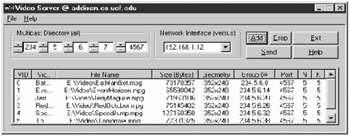
Figure 31.6: Server software— main window.
A user wishing to use the service selects the desired video through a client software called JukeBox (see Figure 31.7). In response, a video player and a control panel pop up (see Figure 31.8); and the selected video is subsequently played out. The client software is built on Microsoft DirectShow and currently supports MPEG-1 system files containing both video and audio tracks. Other file formats supported by DirectShow can also be supported without much modification to the software.
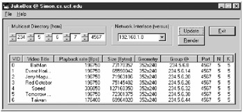
Figure 31.7: Client software— JukeBox.
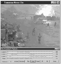
Figure 31.8: Playback of a video.
Experiments with the prototype on a local area network were conducted. Four video clips, each over 5 minutes long, were repeatedly broadcast in these experiments. The number of jitters observed was very small (less than three per playback). This problem was due to packet loss, not a result of the broadcast technique. Each jitter was very brief. The playback quality was comparable to that of commercial streaming systems. The service delays were measured to be less than 13 seconds.
3.2 Client-Oriented Approach: Increasing Client Bandwidth
All the broadcast techniques, discussed so far, aim at enabling the users to improve service latency by adding only server bandwidth. In this subsection, we discuss techniques that require increases to both server and client bandwidth in order to improve system performance.
3.2.1 Cautious Harmonic Broadcasting
Cautious Harmonic Broadcasting [22] partitions each video into K equally sized segments. The first channel repeatedly broadcasts the first segment S1 at the playback rate. The second channel alternatively broadcasts S2 and S3 at half the playback rate. Each of the remaining segments Si is repeatedly broadcast on its dedicated channel at 1/(i-1) the playback rate. Although this scheme uses many channels to deliver a video, the total bandwidth grow slowly following the harmonic series, typically adding up to only 5b or 6b.
A client plays back a video by downloading all the segments simultaneously. This strategy has the following drawbacks:
-
The client must match the server bandwidth allocated to the longest video. The requirement on client bandwidth is therefore very high making the overall system very expensive.
-
Improving access delay requires adding bandwidth to both server and client bandwidth. This makes system enhancement very costly.
-
Since the client must receive data from many channels simultaneously (e.g., 240 channels are required for a 2-hour video if the latency is kept under 30 seconds), a storage subsystem with the capability to move their read heads fast enough to multiplex among so many concurrent streams would be very expensive.
3.2.2 Pagoda Broadcasting
As in the Harmonic scheme, Pagoda Broadcasting [23] also divides each video into equally sized segments. However, it addresses the problems of having too many channels by allowing segments to share channels. The number of segments allocated to each channel is determined according to the following series:
{1, 3, 5, 15, 25, 75, 125, … }
Since the numbers grow very fast in the above series, this scheme requires much less channels than in the Harmonic Broadcasting. The segments assigned to a channel do not have to be consecutive. An example is given in Figure 31.9. It shows that 19 segments are repeatedly broadcast on four channels. The idea is to broadcast each segment at least once every period in term of the Harmonic Broadcast scheme.
| 1st Stream | S1 | S1 | S1 | S1 | S1 | S1 | S1 | S1 | S1 | S1 |
| 2nd Stream | S2 | S4 | S2 | S5 | S2 | S4 | S2 | S5 | S2 | S4 |
| 3rd Stream | S3 | S6 | S8 | S3 | S7 | S9 | S3 | S6 | S8 | S3 |
| 4th Stream | S10 | S11 | S12 | S13 | S14 | S15 | S16 | S17 | S18 | S19 |
Figure 31.9: A broadcast example in Pagoda Broadcast.
Each channel broadcasts data at the playback rate. A client requesting a video downloads data from all the channels simultaneously. The benefit of Pagoda Broadcasting is to achieve a low server bandwidth requirement as in Harmonic Broadcast without the drawback of using many channels. Pagoda Broadcasting, however, has not addressed the high demand on client bandwidth. For instance, keeping service delay less than 138 seconds for a 2-hour video requires each client to have a bandwidth five times the playback rate. Furthermore, performance enhancement or adding a longer video to the database may require the clients to acquire additional bandwidth. In comparison with the Server-Oriented Approach, presented in Section 3.1, the savings in server bandwidth under Pagoda Broadcasting is not worth the significantly more expensive client hardware. Nevertheless, this scheme can be used for local-scale applications, such as corporate training and campus information systems, which rely on an intranet for data transmission.
EAN: 2147483647
Pages: 393