14.3 Models
14.3 Models
With nT transmit and nR receive antennas, a baseband discrete-time model for the multiantenna channel with frequency-flat fading [18] is
| (14.1) |
where x is the nT-dimensional vector representing the transmit signal and y is the nR-dimensional received vector. The vector n, containing both thermal noise and interference, is modeled as Gaussian with zero-mean independent components and power σ2 per receive antenna. [19] The channel, in turn, is represented by the (nR nT) random matrix ![]() containing the transfer coefficients from each transmit to each receive antenna. For convenience, we choose to factor out the scalar
containing the transfer coefficients from each transmit to each receive antenna. For convenience, we choose to factor out the scalar ![]() so as to yield a normalized channel H, the second-order moment of whose entries is unity.
so as to yield a normalized channel H, the second-order moment of whose entries is unity.
We define also the ratio
| (14.2) |
The transmit power is constrained to some value P and thus
| (14.3) |
While power control proved to be an essential ingredient in telephony systems, where source rate variability was minimal, in mobile data systems rate adaptation becomes not only an attractive complement, but even a full alternative to power control. [20] Hence, we restrict ourselves to the case where the total transmit power is held constant while the data rate is being adapted.
The thermal noise power per receive antenna is σ2 = N0BF, where N0 is the onesided noise spectral density, B is the signal bandwidth, and F is the receiver noise figure. We set the noise figure to an optimistic value of F = 3 dB and use the noise spectral density corresponding to a standard temperature of 300 K. In line with the 3G framework, the available bandwidth is set to B = 5 MHz.
Within the channel, [21] different levels of randomness exist:
-
The large-scale randomness associated with distance decay, shadow fading, etc., determines the average conditions at every location. Its impact is absorbed into the path gain g, which has a coherence distance of tens or even hundreds of wavelengths, and thus can be regarded as deterministic within a local area. The path gain has a range-dependent component, which we model using the well-established COST231 model, [22] and a shadow fading component, which is taken to be log-normally distributed with an 8-dB standard deviation. [23] In suburban environments at 2 GHz, the average path gain is given by [24]
(14.4) 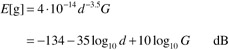
d where the expectation is over the shadow fading, the range in km and G the total (combined transmit and receive) antenna gain.
-
The small-scale randomness caused by multipath propagation can be modeled as a locally stationary random process. This level of randomness, contained within H, has a coherence distance that is on the order of a wavelength. Because the small-scale fading encountered in wireless systems tends to be Rayleigh in distribution, the entries of H can be realistically modeled as zero-mean complex Gaussian random variables. [25] With that, the characterization of H entails simply determining the correlation between its entries. A typical propagation scenario, portrayed in Figure 14.1, contains an area of local scattering around each terminal with little or no local scattering around the elevated base stations. [26] As a consequence of this local scattering, antennas mounted on a terminal can be presumed, to first order, to be mutually uncorrelated even when the physical separation between antennas is as small as a fraction of wavelength. From the perspective of a base station, the angular distribution of power that gets scattered to every terminal is much narrower, characterized by its root-mean-square width or angular spread. Typical values for the angular spread at a base station are in the range of 1 to 10 degrees, depending on the environment and range. [27] With such narrow spreads, ensuring low levels of correlation between those antennas may require larger physical separation (typically a few wavelengths) or the use of orthogonal polarizations, [28] but to first order we can again model them as uncorrelated.
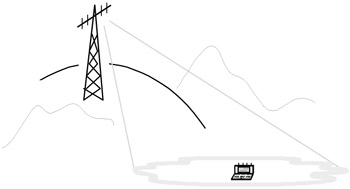
Figure 14.1: Propagation scenario with local scattering around the terminal spanning a certain azimuth angle spread at the base station.
Most wireless systems are equipped with pilots that are needed for synchronization, identification, and a number of other purposes, and which may be used also to obtain an estimate of the channel. Therefore, accurate information about H can be gathered by the receiver. [29] Consequently, throughout the chapter we focus on those scenarios wherein H is known to the receiver. [30] The transmitter, however, is presumed unaware of the state of the channel for otherwise a heavy burden would be placed on the system in terms of fast feedback requirements.
At the receiver, the SINR is given by
| (14.5) |  |
We shall concentrate mostly on the downlink, which has the most stringent demands for Internet access, but occasional references to the uplink will be made as well. The analysis of both links is quite similar, with the exception of much tighter transmit power constraints for the uplink, which originates at the terminal. In terms of system structure, a cellular layout with fairly large hexagonal cells is assumed, with every cell partitioned into three equal-sized sectors.
[18]The analysis and results to follow can be extended to the more general case of frequency-selective fading.
[19]While thermal noise is inherently white, interference tends to be spatially colored, and thus its components are not necessarily independent. Nonetheless, for the sake of simplicity the entire vector n can be modeled as white to yield a lower bound on the bandwidth efficiency.
[20]Goldsmith, A.J. and Varaiya, P., Capacity of fading channels with channel side information, IEEE Trans. Information Theory, 1985–1992, Nov. 1997.
[21]Cox, D.C., Universal digital portable radio communications, Proc. IEEE, 75 (4), 436–477, 1987.
[22]European Corporation in the Field of Scientific and Technical Research EURO-COST 231, Urban Transmission Loss Models for Mobile Radio in the 900 and 1800 MHz Bands, Revision 2, The Hague, Sept. 1991.
[23]Cox, D.C., Universal digital portable radio communications, Proc. IEEE, 75 (4), 436–477, 1987.
[24]The base station and terminal heights are set to 35 and 2 m, respectively. The path gain can be adjusted for other types of environment and frequency bands.
[25]Channels that are non-Gaussian and behave abnormally may in theory occur. (*Chizhik, D. et al., Keyholes, Correlations and capacities of multielement transmit-and-receive antennas, IEEE Trans. Wireless Commun., 2 (1), 361–368, 2002.), (**Dietrich, C.B. Jr. et al., Spatial, polarization, and pattern diversity for wireless handheld terminals, IEEE Trans. Antennas Propagation, 49 (9), 1271–1281, 2001.)
[26]Local scattering around the base stations would only reinforce the model.
[27]Chu, T.-S. and Greenstein, L.J., A semiempirical representation of antenna diversity gain at cellular and PCS base stations, IEEE Trans. Commun., 45–46, June 1997.
[28]Gesbert, D. et al., MIMO Wireless Channels: Capacity and Performance Prediction, Proc. IEEE GLOBECOM'00, San Francisco, Dec. 2000.
[29]Marzetta, T.L., BLAST Training: Estimating Channel Characteristics for High Capacity Space-Time Wireless, Proc. 37th Annual Allerton Conference on Communication, Control, and Computing, Monticello, Illinois, Sept. 1999.
[30]If the channel changes so rapidly that it cannot be properly estimated, a different class of multiantenna techniques based on differential encoding can be applied. (*Marzetta, T.L. and Hochwald, B.H., Capacity of a mobile multiple-antenna communication link in Rayleigh flat fading, IEEE Trans. Inf. Theory, 45 (1), 139–157, 1999.), (**Hochwald, B.H. and Marzetta, T.L., Unitary space-time modulation for multiple-antenna communications in Rayleigh flat fading, IEEE Trans. Inf. Theory, 46, 543–564, Mar. 2000.), (***Hassibi, B., Cayley Codes for Multiple-Antenna Differential Modulation, Proc. Asilomar Conference on Signals, Systems, and Computers, Pacific Grove, California, Vol. 1, Nov. 2001.) Although inferior in potential to the coherent techniques discussed in the chapter, these schemes could be relevant to certain services and applications such as high-speed trains, etc.
EAN: 2147483647
Pages: 239