Using Layers to Organize Your Drawing
Using Layers toOrganize Your Drawing
Overview
- Creating new layers
- Assigning a color and a linetype to layers
- Moving existing objects onto a new layer
- Controlling the visibility of layers
- Working with linetypes
In precomputer days, drafters used sets of transparent overlays on their drafting tables. These were sheets that stacked on top of one another, and the drafters could see through several at a time. Specific kinds of information were drawn on each overlay, all related spatially so that several overlays might all be drawn to the same floor plan. Each overlay had small holes punched near the corners so the drafter could position it onto buttons, called registration points, that were taped to the drawing board. Because all overlays had holes punched at the same locations with respect to the drawing, information on the set of overlays was kept in alignment.
To help you organize your drawing, AutoCAD provides you with an amazing tool, called layers, which is a computerized metaphor for the transparent overlays, only much more powerful and flexible. In manual drafting, you could use only four or five overlays at a time before the information on the bottom overlay became unreadable. In AutoCAD, you are not limited in the number of layers you can use. You can have hundreds of layers, and complex CAD drawings often do.
Layers as an Organization Tool
To understand what layers are and why they are so useful, think again about the transparent overlay sheets used in hand drafting. Each overlay is designed to be printed. The bottom sheet may be a basic floor plan. To create an overlay sheet for a structural drawing, the drafter traces over the lines of the floor plan that they need in the overlay and then adds new information pertinent to that sheet. For the next overlay, the same thing is done again. Each sheet, then, contains some information in common, in addition to data unique to that sheet.
In AutoCAD, using layers allows you to generate all the sheets for a set of overlays from a single file (see Figure 6.1). Nothing needs to be drawn twice or traced. The wall layout will be on one layer and the roof lines on another. Doors will be on a third. You can control the visibility of layers so that all objects residing on a layer can be made temporarily invisible. This feature lets you put all information keyed to a particular floor plan in one .dwg file and from that drawing, to produce a series of derived drawings, such as the foundation plan, the second floor plan, the reflected ceiling plan, and the roof plan, by making different combinations of layers visible for each drawing. When you make a print, you decide which layers will be visible. Consequently, in a set of drawings, each sheet based on the floor plan will display a unique combination of layers, all of which are in one file.
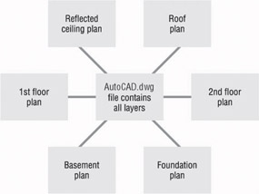
Figure 6.1: A diagram of several drawings coming from one file
Layers, as an organization tool, allow you to classify the various objects in a computerized drawing—lines, arcs, circles, and so on—according to the component of the building they represent, such as doors, walls, and windows. Each layer is assigned a color, and all objects placed on the layer take on that assigned color. This lets you easily distinguish between objects that represent separate components of the building (see Figure 6.2). And you can quickly tell what layer a given object or group of objects is on.

Figure 6.2: Separate layers combined to make a drawing
First, we’ll look at the procedure for achieving this level of organization, which is to set up the new layers and then move existing objects onto them. Following that, you will learn how to create new objects on a specific layer.
Setting Up Layers
All AutoCAD drawings have one layer in common—the 0 layer. The 0 layer is the default layer in all new drawings. If you don’t add any new layers on a drawing, everything you create in that drawing will be on the 0 layer. Everything so far in the cabin drawing has been drawn on the 0 layer.
Objects and layers are analogous to people and countries: Just as all people must reside in some country, so must all objects be on some layer.
All objects in AutoCAD are assigned a layer. In this book, I will refer to objects assigned to a particular layer as “being on” that layer. You can place objects on a layer in two ways: you can move them to the layer, or you can create them on the layer in the first place. You will learn how to do both in this chapter. But first you need to learn how to set up layers. To see how this is done, you will create seven new layers for your cabin drawing—Walls, Doors, Steps, Balcony, Fixtures, Headers, and Roof—and then move the existing objects in your drawing onto the first five of these layers. After that, you will create new objects on the Header and Roof layers. Let’s begin by creating a few new layers.
- Open AutoCAD, and then open Cabin05b.dwg. The Layers toolbar should be just above the drawing area on your screen on the left, and contains three buttons and a drop-down list for controlling layers. (The LT Layers toolbar has only two buttons.)

To the right is the Properties toolbar with four drop-down lists for controlling linetypes, colors, and other layer properties. These are the default positions for these toolbars, but your screen may have a different arrangement.

A linetype is the appearance style of a line, such as continuous, dashed, dash-dot, and so on.
- Click the Layer Properties Manager button on the left end of the Layers toolbar to open the Layer Properties Manager dialog box (see Figure 6.3). Notice the large open area in the middle right of the dialog box with the 0 layer listed at the top. This is called the Layer List box. All the layers in a drawing are listed here, along with their states and properties. For Cabin5b, there is only one layer so far.
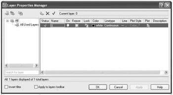
Figure 6.3: The Layer Properties Manager dialog box
The Layer Properties Manager Dialog Box
To the left of the Layer List box is the Layer Filters tree view box. Each box has three icons and buttons above it, and there are two check boxes and four buttons at the bottom of the dialog box. Before setting up new layers, look for a moment at the Layer List box.
We’ll look more closely at the Layer Filters tree view box in Chapter 12.
The Layer List Box
Each layer has four properties: Color, Linetype, Lineweight, and Plot Style. Look at the 0 layer row in the list, and notice the square and the word White in the Color column. The square is black (or white if you have a black background for your drawing area), but the name of the color is White whether the square is black or white. Continuous is in the Linetype column. This tells us that the 0 layer has been assigned the color White (black or white) and the Continuous linetype by default.
| Note |
If you set up your drawing area so that the background is white, AutoCAD automatically changes the color assigned to White in the Layer List box to black, so lines that would normally appear as white on a black background now appear as black on the white background. When you then switch to a black background, the black line changes to a white line. This allows the line to be visible regardless of the background color, and AutoCAD doesn’t have to assign a new color to a layer that has been assigned the White color when the user switches background colors. |
The five columns to the left of the Color column are titled Status, Name, On, Freeze, and Lock. They have picture icons or text in the 0 layer row. These columns represent some of the status modes—or states—of the layer and control whether objects on a layer are visible, whether they can be changed, or whether a layer actually has objects on it. I’ll discuss the visibility and status of layers later in this chapter, and I’ll discuss the columns to the right of the Linetype column—Line, Plot Style, Plot, and Description—in Chapter 14. Don’t worry about them right now.
Creating New Layers and Assigning Colors
Let’s create a few new layers, name them, and assign them colors.
- Just above the Status column, click the New Layer icon. A new layer called Layer1 appears in the list. The layer’s name is highlighted, which means that you can rename it by entering another name now.
- Type Walls. Layer1 changes to Walls. The row for the Walls layer should still be highlighted (see Figure 6.4).
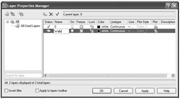
Figure 6.4: The Layer Properties Manager dialog box with a new layer named Walls - Click the word White in the Color column for the Walls row to open the Select Color dialog box (see Figure 6.5). Notice the three tabs at the top—Index Color, True Color, and Color Books. Be sure the Index Color tab is selected and on top. There are three sets of color swatches and two buttons for making color choices. In the row of 9 color swatches, below the large group of 240 choices, click the cyan (turquoise) square. In the Color text box, white changes to cyan, and one of the rectangles in the lower-right corner takes on the color cyan.
For LT users, your Select Color dialog box has only one tab—the Index Color tab—which is the one we’ll be using in this book.
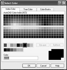
Figure 6.5: The Index Color tab in the Select Color dialog box - Click OK to close the Select Color dialog box. In the Layer List box of the Layer Properties Manager dialog box, you can see that the color square for the Walls layer has changed to cyan.
As you create your new list of layers and assign them colors, notice how each color looks in your drawing. Some are easier to see on a screen with a light background, and others do better against a dark background. In this book, I will be assigning colors that work well with a black background. If your system has a white background, you might want to use darker colors, which can be found in the array of 240 color swatches in the upper half of the Index Color tab.
Let’s continue creating new layers and assigning them colors. You’ll master this procedure as you add a new layer or two in each chapter throughout the rest of the book.
- In the Layer Properties Manager dialog box, click the New Layer icon.
- Type Doors to change the name of the layer.
- Pick the color square in the Doors row. When the Select Color dialog box opens, click the red square in the same row of color swatches where you previously found cyan. Click OK.
- Repeat these steps, creating each of the following layers with their assigned colors. Pick the colors from the same row of color swatches that you have been using.
Layer Name
Color
Steps
9 (Light Gray)
Balcony
Green
Fixtures
Magenta
Headers
Yellow
Roof
Blue
Tip The color blue may or may not read well on a black background. If you don’t like the way it looks, try picking a lighter shade of blue from the array of 240 colors on the Index Color tab.
When finished, the layer list should have eight layers with their assigned colors in the color squares of each row (see Figure 6.6). All layers are assigned the Continuous linetype by default. This is convenient because most building components are represented in the floor plan by continuous lines, but the roof— because of its position above the walls—needs to be represented by a dashed line. Later you will assign a Dashed linetype to the Roof layer.
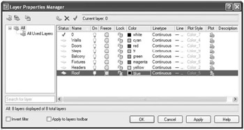
Figure 6.6: The Layer List box, in the Layer Properties Manager dialog box, with the seven new layers and the 0 layer
Naming Layers
You can name layers in a variety of ways. With their different color assignments, layers make it possible for you to easily distinguish which objects in your drawing represent walls or other parts of your building. Most offices follow a standard for organizing layers by name, color, and linetype. The American Institute of Architects publishes Layering Standards, which are often adapted by architecture firms and customized to fit their specific needs. Before AutoCAD version 2000, lineweights in AutoCAD drawings were controlled by color, so the layer standards were developed around this determining factor. Since version 2000, this is no longer the case. As a result, you can expect that layering standards used for years will be changing. With the cabin drawing, you will start out developing a basic set of layers. Once you learn how to manage the set we are using here, tackling more complex layering systems will come naturally.
| Note |
When you name layers, you can use upper- and lowercase letters, and AutoCAD will preserve them. But AutoCAD does not distinguish between them and treats Walls, WALLS, and walls as the same layer. |
Using AutoCAD’s Traditional Colors
The traditional set of 255 colors for AutoCAD is set up in such a way that the first 7 colors are named (Blue, Red, and so on) and numbered (1 through 7), while the other 248 colors only have numbers.
As you saw on the Index Color tab of the Select Color dialog box, there are three groupings of colors: a large array of swatches in the top half, and two rows of them below. Moving the cursor over a swatch displays its AutoCAD number below the array, as well as its RGB values. Click a swatch to assign it to the layer that has been selected in the Layer Properties Manager dialog box.
The array of 240 colorsIn the top half of the dialog box are colors numbered 10 through 249, arranged in an array of 24 columns, each having 10 swatches.
The row of 9 standard color swatchesThis group includes colors 1 through 9.The first 7 colors in this group also have names: Red (1),Yellow (2), Green (3), Blue (4), Cyan (5), Magenta (6), and White/Black (7). Colors 8 and 9 have numbers only. Color 7 is named White, but will actually be black if you are using a white background color.
The row of 6 gray shadesThese are colors that are often assigned screening values (such as 50%, 75%, and so on), numbering 250 through 255. As pure color assignments, they range from almost black to almost white.
These 255 colors, plus the background color, make up the traditional AutoCAD 256-color palette. Two additional colors are in a group by themselves, Logical Colors, and are represented by buttons on the Index Color tab.
The two buttons in this grouping—ByLayer and ByBlock—represent two ways that a color can be assigned to objects—such as lines, circles, text, and so on—via the layer they are on or via the block they are part of, rather than to the objects themselves. (Blocks are covered in the next chapter.) When you assign the color cyan to the Walls layer and place all objects representing walls on that layer, all wall objects are automatically assigned the color ByLayer and take on the color of their layer, in this case, cyan.
In more complex drawings, you might need several layers for variations of the same building component, landscape element, or machine part. The Walls layer, for example, might be replaced by several layers, such as Existing Walls to Remain, Walls to Be Demolished, and New Walls. Once you acquire the skills presented here, you will have no difficulty progressing to a more complex layering system.
Looking at the Other Tabs in the Select Color Dialog Box
|
|
AutoCAD also supports a True Color palette and various PANTONE color groups. Although I won’t cover these features in any depth in this book, let’s take a quick look at them before we move on. |

This section applies only to AutoCAD. LT users should skip to the next section, “Assigning Line Types to Layers.”
The True Color TabWith the Layer Properties Manager dialog box open, click one of the color swatches in the Layer List box to open the Select Color dialog box again. Then click the True Color tab. In the upper-right corner, the Color Model drop-down list will display either RGB or HSL. The RGB (for Red, Green, Blue) color model looks like Figure 6.7a, and the HSL (Hue, Saturation, Luminance) model looks like Figure 6.7b.
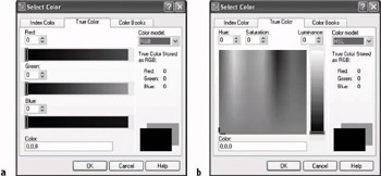
Figure 6.7: The True Color tab with the RGB color model (a) and the HSL color model (b)
The RGB screen shows three horizontal color bands, one for each of the three primary colors. Move the sliders on each band to set a number from 0 to 255, or type a number in the counter box for each color. The three numbers that make up a color are displayed at the bottom and on the right side, and the rectangles in the lower-right corner show the currently selected and previously selected color.
The HSL screen displays a rectangle of colors and a vertical band with a slider. Click and drag the crosshair around on the rectangle. The color in the front rectangle in the lower-right corner changes as you move the crosshair. Moving it left or right takes the hue through a range of 360 values. Moving it up or down changes the percentage of saturation, or intensity, with the top of the rectangle representing 100%.
The slider to the right of the rectangle controls the luminance, which, like saturation, varies from 0%—representing the color black—to 100%, or white. A luminance of 50% maximizes a color’s brightness.
The Color text box displays the currently selected color’s three RGB numbers. You can also specify a color by entering numbers in the individual boxes for hue, saturation, and luminance—or the boxes for red, green, and blue in the RGB screen. And you can use the Up and Down arrows in these boxes to scroll through the possible settings.
If you select a color using the RGB or HSL screens, it is displayed in the Layer List box of the Layer Properties Manager dialog box by its three RGB numbers.
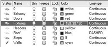
The Color column might be compressed in such a way that the names of colors in the list may be abbreviated. You can widen the column by clicking and dragging the divider at the right of the title farther to the right.
With the combination of 255 values for each of the three primary colors, you now have more than 16 million colors to choose from in AutoCAD.
The Color Books TabThe Color Books tab displays the colors of the selected color book (see Figure 6.8a). AutoCAD has nine color books, and you can load more. Each book is listed in the Color Book drop-down list at the top of the tab with the current book being displayed in the box. Below that, a set of colors that corresponds to the position of the slider is displayed in bars. Moving the slider to a new position displays another set of colors. Click a displayed color bar to select it, and then click OK. The color is displayed in the Layer Properties Manager Layer List box by its identifying name and number (see Figure 6.8b).
Later in the book, you will be asked to create new layers and assign them colors of your choice. Use this opportunity to explore the True Color and Color Books tabs of the Select Color dialog box, and try using some of these colors in your drawing. Keep the Layer Properties Manager dialog box open. You will use it to assign linetypes in the next section.
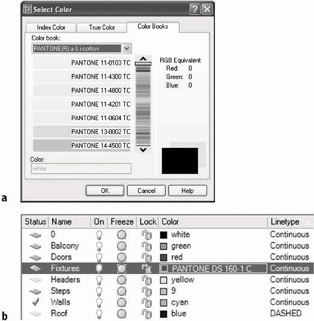
Figure 6.8: The Color Books tab in the Select Color dialog box (a), and the Layer List with an assigned PANTONE number (b)
Assigning Linetypes to Layers
When you assign a color to a layer, you can choose any color supported by your system. Not so with linetypes. Each new drawing has only one linetype loaded into it by default (the Continuous linetype). You must load in any other linetypes you need from an outside file.
- In the Layer Properties Manager dialog box, click Continuous in the row for the Roof layer to open the Select Linetype dialog box (see Figure 6.9). In the Loaded Linetypes list, only Continuous is displayed. No other linetypes have been loaded into this drawing.
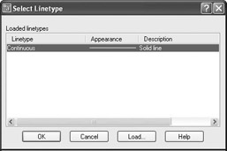
Figure 6.9: The Select Linetype dialog box - Click Load to open the Load Or Reload Linetypes dialog box. Scroll down the list to the Dashed, Dashed2, and DashedX2 linetypes (see Figure 6.10). Notice how, in this family, the dashed lines are different sizes.
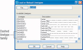
Figure 6.10: The list scrolled to the three Dashed linetypes - Click the word Dashed in the left column, and then click OK. You are returned to the Select Linetype dialog box. The Dashed linetype has been added to the Linetype list under Continuous (see Figure 6.11). Click Dashed to highlight it and click OK. In the Layer Properties Manager dialog box, the Roof layer has been assigned the Dashed linetype (see Figure 6.12).
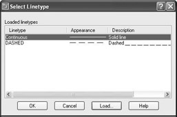
Figure 6.11: The Select Linetype dialog box with the Dashed linetype loaded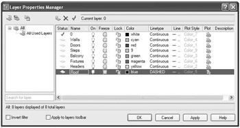
Figure 6.12: The Layer Properties Manager dialog box with the Roof layer assigned the Dashed linetype
AutoCAD’s Linetypes
In the Available Linetypes list in the Load Or Reload Linetypes dialog box, 45 linetypes are listed. They fall into three groups.
Acad_ISO The first 14 linetypes are in the Acad_ISO family (International Organization for Standardization). They are set up to be used in metric drawings and have lineweight, or pen-width, settings.
Standard AutoCAD Below the ISO linetypes are eight families of three linetypes each, mixed with seven special linetypes that contain graphic symbols. Each family has one basic linetype and two that are multiples of it: one has dashes twice the size (called, for example, Dashed2), and one has dashes half the size (called Dashed2). (See Figure 6.10, shown earlier.) Having an assortment of different sizes of one style of linetype is helpful for distinguishing between building components, such as foundation walls and beams, which, in addition to roof lines, may also need dashed lines.
Complex Mixed in with the Standard linetypes are seven linetypes that contain symbols, letters, or words. These are used to indicate specific elements in the drawing, such as fences, hot-water lines, railroad tracks, and others.
It is not difficult to create your own custom linetypes. You can do so in two ways.
Using Notepad Start the Notepad program and navigate to the Support folder for AutoCAD 2004, usually found at this location: C:Documents & Settingsyour nameApplication DataAutodesk AutoCAD 2005 [or AutoCAD LT 2005]R16.0enusupport. Open the file named acad whose type is listed as “AutoCAD Linetype Definition.” Its full name is acad.lin. It contains the definition codes for all the linetypes, and they are easy to figure out. Copy an existing pattern and create your own.
Using the Linetype Command Type -linetype, and then type c for the Create option. You will be guided through the steps to create your own .lin file or add to an existing file. To use the Linetype command, you need to know the definition codes. Use Notepad until you get a feel for the codes.
A Word about Lineweight
In the Layer Properties Manager dialog box is a column for the Lineweight property. When you first create a layer, it is assigned the default lineweight. Just as you assigned a color and a linetype for each new layer in the cabin drawing, you can also assign a lineweight. Once assigned, lineweights can be displayed so you can see how your drawing will look when printed. In Chapter 14 you will learn more about lineweights, about how to assign them to layers, and about how to view your drawing as it will look when printed or in WYSIWYG mode.
The Current Layer as a Drawing Tool
Now is a good time to look at what it means for a layer to be current. Notice the green check mark icon above the Layer List box in the Layer Properties Manager dialog box. The name of the current layer, in this case, 0, is displayed just above the Layer List box next to the green check mark.
At any time, one, and only one, layer is set as the current layer. When a layer is current, all objects you draw will be on that layer and will take on the properties assigned to it. Because the 0 layer is current—and has been current so far in this book—all objects that you have drawn so far are on the 0 layer and have the linetype and color that are specified by default for the 0 layer: Continuous and White (or Black), respectively. If you make the Walls layer current, any new lines you draw will be Cyan and Continuous. If the Roof layer is current, any new lines will be Blue and Dashed.
- Click the Walls layer in the Layer List box to highlight it. Then click Current. The Walls layer replaces the 0 layer as the current layer.
- Click OK to close the Layer Properties Manager dialog box and return to your drawing.
- Look at the Layer Control drop-down list on the Object Properties toolbar. Most of the symbols you saw in the Layer List box, in the Layer Properties Manager dialog box, are on this drop-down list. The Walls layer is the visible entry on the list and has a cyan square (the color you assigned to the Walls layer earlier). The layer visible in this list when it is closed and no objects are selected is the current layer.

- Now look at your drawing. Nothing has changed because the objects in the drawing are still on the 0 layer.
You need to move the objects in the drawing onto their proper layers. To do this, you’ll use the Layer Control drop-down list on the Object Properties toolbar to assign each object to one of the new layers.
Assigning Objects to Layers
When assigning existing objects in the drawing to new layers, our strategy will be to begin by selecting all the objects that belong on the same layer and that are easiest to select. We’ll reassign them to their new layer, using the Layer Control drop-down list. We’ll then move to a set of objects that belong on a different layer and are slightly more difficult to select, and so on.
- In the drawing, pick the two arcs of the balcony. Grips appear on the arcs, and the lines ghost. This signals that the lines have been selected (see Figure 6.13).
Notice also that in the Layer Control drop-down list, the layer being displayed now is the 0 layer rather than Walls, the current layer. When objects are selected with no command running, the Layer Control drop-down list displays the layer to which the selected objects are currently assigned. If selected objects are on more than one layer, the Layer Control drop-down list goes blank.
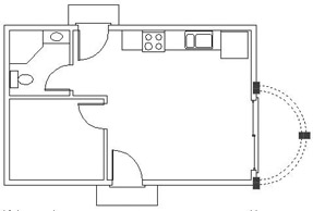
Figure 6.13: The balcony arcs, selected and displaying their grips - Click the Layer Control drop-down list to open it (see Figure 6.14).
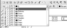
Figure 6.14: The opened Layer Control drop-down list - Click the Balcony layer. The list closes. The Balcony layer is displayed in the Layer Control drop-down list. The balcony arcs have been moved to the Balcony layer and are now green.
- Press Esc to remove the grips. The current layer, Walls, returns to the Layer Control drop-down list.
This is the process you need to go through for each layer so that the new layers can receive objects that are currently on the 0 layer. In the next section, we’ll move the threshold and steps to the Steps layer. You will select the threshold and steps by using a selection window.
Selecting Objects with Windows
AutoCAD provides many tools for selecting objects in your drawing. Two of the most powerful are the crossing and regular selection windows. You determine the size and location of these selection windows by picking points on your drawing to be opposite corners of a rectangle that will serve as the window. The regular window selects any objects completely enclosed by the window. The crossing window selects objects that are completely enclosed by or cross through an edge of the window. The crossing window is represented by dashed lines, and the regular window is represented by solid lines.
By default, AutoCAD is set up so that whenever no command is running and the prompt in the Command window is Command:, you can pick objects one at a time or start a regular or a crossing window. If you pick an object, it is selected, and its grips are displayed. If you select a blank area of the drawing, a selection window is started. If you then move the cursor to the right of the point just picked, a regular window is started. If you move the cursor to the left, a crossing window is started. You’ll use a crossing window to select the sliding glass door threshold, and you’ll use two regular windows to select the front and back steps and those thresholds.
- Zoom into the sliding glass door area. Click the Osnap button on the status bar to put it in the off position, if it isn’t already off.
- Hold the crosshair cursor above and to the right of the upper-right corner of the balcony threshold—still inside the balcony wall—as shown in Figure 6.15a. Click that point, and then move the cursor down and to the left until you have made a tall, thin crossing window that completely encloses the right edge of the threshold and is crossed on its left edge by the short horizontal connecting lines, as shown in Figure 6.15b. Then click again. Click the Layer Control drop-down list to open it, and then click the Steps layer. The balcony threshold is now on the Steps layer.
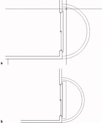
Figure 6.15: Starting the crossing selection window (a), and completing it (b) - Zoom Previous to return to a view of the entire drawing. Make two regular windows to select the front and back steps and their thresholds. Be sure your first pick starts a window at the left and finishes to the right of each step, so the window completely encloses the horizontal and vertical lines that make up each step and threshold. Figure 6.16 illustrates the two regular selection windows and the points to pick to create them. Once selected, the objects display their grips. For lines, grips appear at each endpoint and at the midpoint of each segment. When endpoints of lines coincide or when lines are very short, some of the grips overlap.
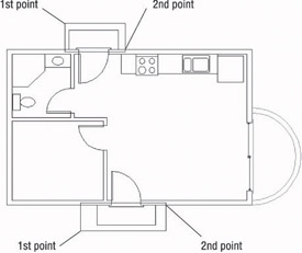
Figure 6.16: The two regular selection windows used to select the front and back steps and thresholds - Click the Layer Control drop-down list, and then click the Steps layer. The front and back steps and their thresholds are now on the Steps layer.
- Press the Esc key to remove the grips.
Grips have uses other than signaling that an object has been selected. You’ll learn about some of these as we progress through the chapters.
Selecting the Doors and Swings
To select the doors and swings, you can use crossing windows. Let’s examine this task closely to learn more valuable skills about how to select objects.
- Place the crosshair cursor in a clear space below and to the right of the back door, and then pick that point to start the selection window. Move the cursor up and to the left until the crossing window crosses the back door and swing, but does not cross the wall line, as shown in Figure 6.17a.
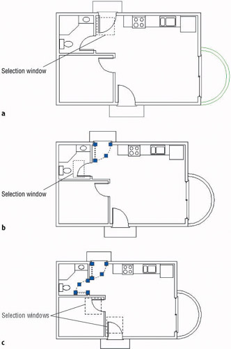
Figure 6.17: Using a crossing window to select the doors and swings: the back door (a), the bathroom door (b), and the bedroom and front doors (c) - When you have the crossing window positioned correctly, click again to select the back door and its swing.
- Move to the bathroom, and position the crosshair cursor in the clear space directly above the swing. When the crosshair is positioned, click. Then move the cursor down and to the left until the window you are creating crosses the bathroom door and swing, without crossing any wall lines (see Figure 6.17b). Then click in a clear space again. The bathroom door and swing are selected.
- Continue this procedure to select the other two doors and their swings. For the bedroom door, start the crossing window directly below the door swing. For the front door, start a crossing window above and to the right of the door. Figure 6.17c shows the two crossing windows that will select the bedroom and front doors.
- Open the Layer Control drop-down list and select the Doors layer. Then press Esc to remove the grips. The swinging doors are now red and on the Doors layer.
For the sliding glass door, it is awkward to create a crossing window from left to right because it may be difficult to position the pickbox between the threshold lines and the sliding door. In this situation, use a regular window to select the objects.
- Zoom in to the sliding glass door area. Pick a point to the left of the balcony opening, just above the upper jamb line. Move the crosshair down and to the right until the right edge of the window sits inside the wall but to the right of the sliding glass window frames. When your window is positioned as shown in Figure 6.18, click. The entire sliding glass door assembly will be selected, but not the jambs, walls, threshold, or balcony. Many grips appear: 13 lines make up the sliding glass door, and each has three grips. Many of the grips overlap.
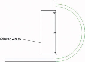
Figure 6.18: Using a regular selection window to select the sliding glass door - Open the Layer Control drop-down list and select the Doors layer. Back in your drawing, all doors are the color red and are on the Doors layer.
- Press Esc to remove the grips, and then Zoom Previous. You will have a full view of the floor plan.
The next task is to move the kitchen and bathroom counters and fixtures onto the Fixtures layer. In doing this, you’ll learn how to deselect some objects from a group of selected objects.
Selecting the Kitchen and Bathroom Fixtures
Sometimes it is more efficient to select more objects than you want and then deselect those you don’t want. You’ll see how this is done when you select the kitchen and bathroom fixtures.
- Pick a point in the kitchen area just below the refrigerator to start a crossing window.
- Move the cursor to the left and up until the upper-left corner of the crossing window is to the left of the left edge of the counter and inside the back wall, as shown in Figure 6.19a. When you have it correct, click that point. The entire kitchen counter area and the back wall line are selected.
- Now move over to the bathroom and pick a point in the middle of the bathroom sink, being careful not to touch any lines with the crosshair cursor.
- Move the crosshair cursor down and to the left until the lower-left corner of the crossing window is in the middle of the toilet tank (see Figure 6.19b). When you have it positioned this way, click that point. All the bathroom fixtures and the door swing are selected.
- Hold down the Shift key and then pick the selected door swing in the bathroom and the back wall line in the kitchen. As you pick them, their lines become solid again, letting you know they have been deselected, or removed from the selection set, but their grips remain (see Figure 6.19c). Be sure to pick the back wall line in the kitchen where it doesn’t coincide with the stove.
- Release the Shift key. Open the Layer Control drop-down list and select the Fixtures layer. The fixtures are now on the Fixtures layer and are magenta in color.
- Press the Esc key to remove the grips.
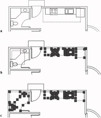
Figure 6.19: A crossing window to select the kitchen objects (a), another crossing window to select the bathroom objects (b), and the completed selection set after removing the door swing and back wall line (c)
The last objects to move onto a new layer are the wall lines. As the drawing is now, it will not be easy to select the wall lines because so many other objects in the drawing are in the way. However, these other objects are now on their own layers, while the wall lines are still on the 0 layer. If you make all your layers temporarily invisible except for the 0 and Walls layers, selecting the wall lines will be easy.
Selecting Objects in Your Drawing
As you select objects in the cabin drawing to move them onto their prescribed layers, you use various selection tools. These tools are important, and mastering them will greatly enhance your performance as an AutoCAD user. As you select objects by picking them and windowing them, you are building a selection set. You might later want to remove objects from that selection set. Here is a summary of the basic selection tools that you have used so far, with a couple of additions.
PickingThis is the basic, bottom-line selection tool. Click the line, circle, or other object to select it. If no command is running, grips appear on the selected object, and the object ghosts. If a command is running and you are being prompted to Select objects:, grips do not appear, but the object is selected and ghosts.
Selecting a Window AutomaticallyTo start a window, click a location that is in an empty portion of the screen, where there are no objects. To form a regular window, move your cursor to the right. To form a crossing window, move your cursor to the left. This feature is called implied windowing, and it works this way if no command is running or if one is running and the prompt line says Select objects:.
If the geometry of your drawing makes forming a crossing or regular selection window difficult because of the need to move from right to left (crossing) or from left to right (regular), you can force one or the other by typing c or w, respectively, but only if a command is running.
Removing Objects from a Selection SetAt some point, you will find it more efficient to select more objects than you want and then remove the unwanted ones. You can do this in two ways:
- To remove a couple of objects, hold down the Shift key and pick the objects.
- To remove many objects, type r, and then use the selection tools (picking, windows, and so on) to remove them from the selection set.
If you need to add objects back to the selection set after removing some, type a. This will put you back into selection mode, and you can continue adding objects to the set.
Turning Off and Freezing Layers
You can make layers invisible either by turning them off or by freezing them. When a layer is turned off or frozen, the objects on that layer are invisible. These two procedures operate the same way and do about the same thing. The difference between freezing and turning a layer off is technical and beyond the scope of this book. However, here is a good rule to follow: if you want a layer to be invisible for only a short time, turn it off; if you prefer that it be invisible semipermanently, freeze it. For the task at hand, we will turn off all the layers except the 0 layer and the Walls layer. We will then move the wall lines onto the Walls layer.
- Click the Layer Properties Manager button on the Object Properties toolbar to open the Layer Properties Manager dialog box. Notice that the 0 layer is still first in the list and that the other layers have been reorganized alphabetically (see Figure 6.20a). Also notice the icons in the Status column: a green check mark signifies that the Walls layer is current; the dark blue layer icons signify that those layers (Balcony, Doors, Fixtures, and Steps) now have objects on them; and the light gray layer icons tell us that those layers (0, Headers, and Roof) do not have any objects on them.
Layers beginning with numbers are listed first, in numeric order. Following those are the rest of the layers listed alphabetically.
Note Because the Walls is current and has a green check mark in the Status column, you can’t tell if it has any objects on it. You have to make another layer current, and then check whether the Walls icon is blue or gray.
- Click the Balcony layer to highlight it. Then hold down the Shift key and click the Steps layer. All layers have been selected except the 0 layer and the Walls layer.
- Move the arrow cursor over to the On column, which has a lit light bulb as a symbol for each layer row.
- Click one of the light bulbs of the selected layers. The lit light-bulb symbols have all changed to unlit bulbs except the ones for the 0 layer and the Walls layer (see Figure 6.20b).
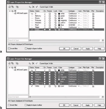
Figure 6.20: The layers, now listed alphabetically (a), and newly turned-off layers (b) - Click OK. All objects in your drawing are invisible except the wall lines (see Figure 6.21). The wall lines are still on the 0 layer.
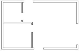
Figure 6.21: The floor plan with all layers frozen except the Walls layer and the 0 layer - Start a regular selection window around the cabin by clicking the upper-left corner of the drawing area, above and to the left of any lines. Then click the lower-right corner in the same way. All the wall lines are selected, and grips appear on all of them.
- Open the Layer Control drop-down list, and then click the Walls layer. The walls move to the Walls layer and are now cyan. Press Esc to remove the grips.
- Click the Layer Properties Manager button on the Object Properties toolbar. In the Layer Properties Manager dialog box, right-click any layer and choose Select All from the shortcut menu. All layers are highlighted.
- Click one of the unlit bulbs in the On column. All unlit bulbs become lit. Click OK. Back in your drawing, all objects are now visible and on their correct layers (see Figure 6.22).
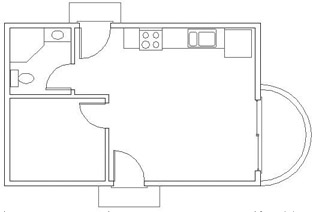
Figure 6.22: The floor plan with all layers visible and all objects on their correct layers - Save this drawing in your training folder as Cabin06a.
Two of your layers, Roof and Headers, still have no objects on them because these components haven’t been drawn yet. We’ll draw the headers now.
Drawing the Headers
Most door and window openings do not extend to the ceiling. The portion of the wall above the opening and below the ceiling is the header. The term comes from the name of the beam inside the wall that spans the opening. In a floor plan, wall lines usually stop at the door and window openings, but you need lines across the gap between jamb lines to show that an opening does not extend to the ceiling; hence, the header.
To draw headers, you need to make the Headers layer current. As you’ve seen, you can use the Layer Properties Manager dialog box. But there is a shortcut, the Layer Control drop-down list, which you have just been using to move objects from one layer to another.
- Click anywhere on the drop-down list or the down-arrow button on the right end. The drop-down list opens, displaying a list of the layers in your drawing. If you have more than 10 layers, a scroll bar becomes operational, giving you access to all the layers.
- Click the Headers layer. The drop-down list closes. Headers is now in the box; this tells you that the Headers layer has replaced Walls as the current layer.
- Right-click the Osnap button on the status bar, and then choose Settings from the shortcut menu to open the Drafting Settings dialog box at the Object Snap tab. Be sure Endpoint is the only Object Snap mode with a check mark, be sure that Object Snap On is checked, and then click OK.
- The doors and steps may be in your way. Click the Layer drop-down list. When the list of layers appears, click the light-bulb icons for the Doors and Steps layers to turn them off. Then click Headers at the top of the list. The drop-down list closes; the Headers layer is still current. The doors, steps, and thresholds have temporarily disappeared.
You need to draw two parallel lines across each of the five openings, from the endpoint of one jamb line to the corresponding endpoint of the jamb on the opposite side of the opening.
- To start the Line command, type L. Move the cursor near the upper end of the left jamb for the back door until the colored square appears at the upper endpoint of the jamb line, then click.
- Move the cursor to the upper end of the right jamb, and do the same thing you did in the previous step.
- Right-click once to open a shortcut menu near your cursor.
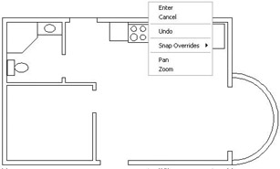
- Choose Enter on the menu, and then right-click again to open another shortcut menu at the cursor.
- Choose Repeat Line.
- Move to the lower endpoint of the right jamb line for the back door and—with the same technique used in steps 5 through 9—draw the lower header line across the opening. The results are shown in Figure 6.23a.
- Keep using the same procedure to draw the rest of the header lines for the remaining four doorway openings. Use a click, click, right-click, click, right-click, click pattern on your mouse that repeats for each header line. Here are the steps:
- Click one of the jamb corners.
- Click the opposite jamb corner.
- Right-click to open a shortcut menu.
- Press to end the Line command.
- Right-click again to open another shortcut menu.
- Choose Repeat Line.
- Click one of the jamb corners.
- And so on.
When you’re finished, use the Layer drop-down list to turn on the Doors and Steps layers. The floor plan will look like Figure 6.23b.
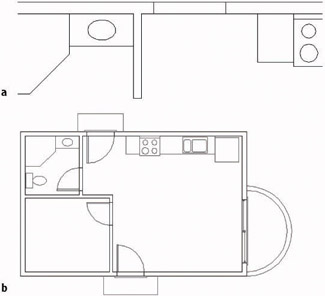
Figure 6.23: The header lines drawn for the back door opening (a), and for the rest of the doorway openings (b)
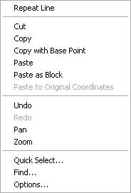
| Note |
Shortcut menus—also called context menus and right-click menus—contain frequently used tools. The specific tools on a menu depend on what you’re doing when you right-click. It was not terribly efficient to use them to draw the header lines, but it was a good way to introduce them to you. It’s also a way to draw without using the keyboard. |
The Layer drop-down list box is a shortcut that allows you to quickly pick a different layer as the current layer and to turn off or turn on individual layers. To create new layers or to turn off many layers at a time, use the Layer Properties Manager dialog box. (Click the Layer Properties Manager button on the Object Properties toolbar.) You’ll learn about another tool for changing the current layer as you draw the roof lines.
Drawing the Roof
Before starting to draw the roof lines, refer to Figure 6.24 and note the lines representing different parts of the roof:
- Four eaves lines around the perimeter of the building, representing the lowest edge of the roof
- One ridgeline, representing the peak of the roof
- Four hip lines, connecting the endpoints of the eaves lines to an endpoint of the ridgeline
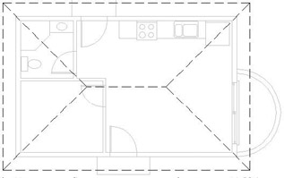
Figure 6.24: The floor plan with the roof lines
The roof for the cabin is called a hip roof because the end panels slope down to the eaves just as the middle panels do. The intersections of the sloping roof planes form the hip lines. We’ll start with the eaves.
Creating the Eaves
Because the roof is cantilevered out beyond the exterior walls the same distance on all sides of the building, we can generate the eaves lines by offsetting the outside wall lines.
- Start the Offset command. Then type 1'6 to set the offset distance. Pick the left outside wall line, and then pick a point to the left of that line to offset it to the outside.
- Move to another side of the building, pick one of the outside wall lines, and offset it to the outside.
- Repeat this for the other two sides of the building until you have offset one outside wall line to the outside of the building on each side of the cabin (see Figure 6.25). Press to end the Offset command. Be sure you have only one line offset on each side of the building. If you offset two lines on one side, erase one.
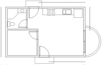
Figure 6.25: One outside wall line is offset to each side of the building. - Type f to start the Fillet command. Make sure that the radius is set to zero. If it is, go to step 5. If not, type r, and then type 0 to reset the radius.
- Click any two of these newly offset lines that are on adjacent sides of the building. Click the half of the line nearest the corner where the two selected lines will meet (see Figure 6.26a). The lines extend to meet each other and form a corner (see Figure 6.26b). The Fillet command ends.
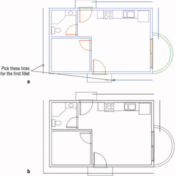
Figure 6.26: Picking lines to fillet one of the eaves’ corners (a), and the result (b) - Press to restart the Fillet command. Pick two more adjacent lines that will meet at another corner.
- Start the Fillet command again, and keep picking pairs of lines until all the corners are filleted and the result is a rectangle that represents the eaves of the roof surrounding the building, offset 1'-6" from the outside exterior walls (see Figure 6.27).
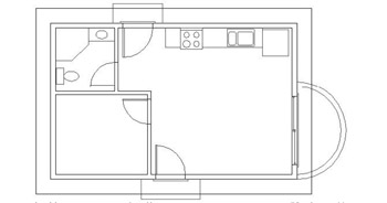
Figure 6.27: The eaves lines after filleting
Because the eaves lines were offset from wall lines, they are on the Walls layer. You need to move them onto the Roof layer. You’ll then make the Roof layer current so that when you draw the hip lines and the ridgeline, they will be on the Roof layer.
- Select the four eaves lines, and then click the Layer Control drop-down list on the Object Properties toolbar.
- Click Roof. The eaves lines are now on the Roof layer.
- Press Esc to remove the grips.
The eaves lines are still solid lines, even though the Roof layer has been assigned a Dashed linetype. Actually, the lines are dashed, but the dashes are so small that the monitor can’t display them.
Setting a Linetype Scale Factor
By default, the dashes are set up to be 1⁄2" long with 1⁄4" spaces. This is the correct size for a drawing that is close to actual size on your screen, like the box you drew in Chapter 2. But for something that is the size of your cabin, you must increase the linetype scale to make the dashes large enough to see. If the dashes were 12" long with 6" spaces, they would at least be visible, though possibly not exactly the right size. To make such a change in the dash size, ask what you must multiply 1⁄2" by to get 12". The answer is 24—so that’s your scale factor. AutoCAD stores a Linetype Scale Factor setting that controls the size of the dashes and spaces of noncontinuous linetypes. The default is 1.00, which gives you the 1⁄2" dash, so you need to change it to 24.00.
- Type ltscale. The prompt in the Command window reads New scale factor <1.0000>:.
- Type 24 to set the linetype scale factor to 24. Your drawing changes, and you can see the dashes (see Figure 6.28).
If you are not satisfied with the dash size, restart the Ltscale command and increase the scale factor for a longer dash or decrease it for a shorter one. This linetype scale factor is a global one, meaning that it affects every noncontinuous line in the drawing. There is also an individual scale factor for linetypes. You’ll see that in the next section.
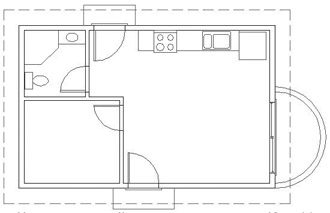
Figure 6.28: The eaves lines on the Roof layer with visible dashes
Assigning an Individual Linetype Scale Factor
Although the Ltscale command sets a linetype scale factor for all noncontinuous lines in the drawing, you can adjust the dash and space sizes for individual lines. If you want to change the dash and space size for one of the eaves lines of the roof to make them larger, follow these steps:
- Select an eaves line to display grips.
- Click the Properties button on the Standard toolbar to open the Properties palette.
- Click Linetype Scale. Highlight the current scale of 1.0000 and type 3.
- Close the Properties palette and press Esc to remove the grips. The dashes and spaces of the previously selected eaves line are three times larger than those for the rest of the roof lines.
- Click the Properties button and use the same procedure to change the current linetype scale factor for the eaves line back to 1.
Note If no objects are selected, and you set Linetype Scale in the Properties palette to a number other than 1.000, any noncontinuous lines that are subsequently drawn will be controlled by this new Linetype Scale.
This tool allows you to get subtle variations in the size of dashes and spaces for individual, noncontinuous lines. But remember that all lines are controlled by an individual linetype scale factor and by the global linetype scale factor. The actual size of the dashes and spaces for a particular line is a result of the two linetype scale factors working together. This additional flexibility requires you to keep careful track of the variations you are making.
To find out the current values for the individual (called object) and global linetype scale factors, follow these steps:
- With Cabin06a as the current drawing, type linetype to open the Linetype Manager dialog box.
- Make sure the Details area is visible at the bottom of the dialog box. If it isn’t, click Show Details in the upper-right corner.
- Note the bottom-right corner. The current global and object linetype scales are displayed here. They can also be modified here.
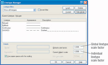
- For now, click Cancel.
Drawing the Hip and Ridge Lines
Next, you’ll draw two of the diagonal hip roof lines and then use the Mirror command to create the other two. To do this, you need to assign the Roof layer as the current layer. Because you have moved the lines you just offset to the Roof layer, you can use the Make Object’s Layer Current button to make the Roof layer current.
- Click the Make Object’s Layer Current button on the Layers toolbar, just to the right of the Layer Control drop-down list. You will get the Select object whose layer will become current: prompt.
- Pick one of the dashed eaves lines. The Roof layer replaces Header in the Layer drop-down list, telling you the Roof layer is now the current layer.
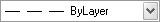
Look at the Linetype Control drop-down list on the Properties toolbar. A dashed line with the name ByLayer appears there. ByLayer tells you that the current linetype is going to be whatever linetype has been assigned to the current layer. In the case of the Roof layer, the assigned linetype is dashed. You will read more about ByLayer at the end of this chapter.
- The Endpoint Osnap should still be running. How can you tell? Type os to open the Drafting Settings dialog box at the Osnap tab. You can easily see which Osnaps are checked. First, be sure Object Snap On is checked. Then, if Endpoint is checked, click the Polar Tracking tab. Otherwise, click the Endpoint check box and then click the Polar Tracking tab (see Figure 6.29).
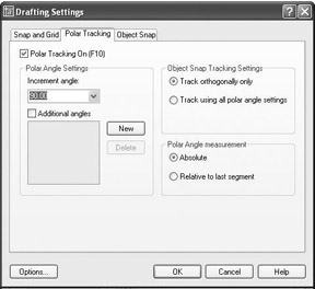
Figure 6.29: The Polar Tracking tab in the Drafting Settings dialog box - At the top, click the Polar Tracking On (F10) check box to turn on Polar Tracking.
- In the Polar Angle Settings area, open the Increment Angle drop-down list and select 45.
- Click OK to close the Drafting Settings dialog box.
- Start the Line command. Move the crosshair cursor to the lower-left corner of the rectangle representing the roof until the square appears on the corner, and then click. A line is started.
- Move the crosshair cursor up and to the right at a 45 angle from the lower-left corner of the roof. When the angle of the line being drawn approaches 45, a tracking path and a Polar tool tip will appear, along with a small x near the crosshair cursor (see Figure 6.30a).
- While the tracking path is visible, type 15'. The first hip line is drawn, and the Line command ends (see Figure 6.30b).
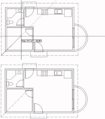
Figure 6.30: The 45 tracking path for the first hip line of the roof (a), and the completed first hip line (b)
Use the same procedure to draw another hip line from the upper-left corner of the roof. Here’s a summary of the steps:
- Restart the Line command, and start a line at the upper-left corner of the roof.
- Hold the crosshair cursor down and to the right at an angle of approximately 45 until the Polar Tracking path with its tool tip appears. (The tool tip will confirm that the actual angle is 315.)
- Type 15’. The second hip line is completed.
The two hip lines need to be filleted together at their intersection, but the bedroom door is in the way.
- Open the Layer Control drop-down list and turn off the Door layer. Then click the Roof layer in the list to close the list.
- Start the Fillet command. The radius should still be set to zero. Click the two diagonal lines at a place that is close to their intersection. The lines are filleted together (see Figure 6.31a). Now you need to mirror these two diagonal lines to the right side of the roof.
- Start the Mirror command. At the prompt to select objects, select the two diagonal lines, and then press . Click the Midpoint Osnap button and place the cursor on the horizontal eaves line above the cabin. When the triangle appears at the midpoint of the eaves line, click.
- Move the crosshair cursor down into the living room, keeping it directly below the point just picked, and when the tracking line and Polar tool tip appear, click in a clear space. Press when asked whether to delete old objects. The diagonal lines from the left are mirrored to the right (see Figure 6.31b). The Mirror command automatically ends. To finish the roof, we’ll draw in the ridgeline.
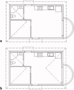
Figure 6.31: The first two hip lines are filleted together (a) and then mirrored to the right (b). - Start the Line command. Endpoint Osnap is still running. Pick the two intersections of the diagonal lines, and then press . Open the Layer Control drop-down list and turn on the Doors layer. Then click the roof layer to close the drop-down list. This completes the ridgeline and finishes the roof (see Figure 6.32). Save this drawing as Cabin06b.
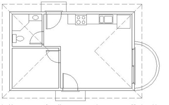
Figure 6.32: The completed roof
By drawing the roof lines, you have completed the exercises for this chapter. The cabin floor plan is almost complete. In the next chapter, you will complete the floor plan by placing windows in the external walls using a new grouping tool called the block. The rest of this chapter contains a short discussion on color, linetypes, and lineweights and how they work with layers and objects.
Properties of Layers and Objects
Here are a few concepts to consider when assigning properties to layers and objects.
Selecting Colors for Layers and Objects
First, you must decide whether you prefer a light or dark background color for the drawing area. This is generally a personal preference, but the lighting in your work area can be a contributing factor. Bright work areas usually make it difficult to read monitors easily, and with a dark background color on your screen in a brightly lit room, you will often get distracting reflections on the screen. Eyestrain can result. Darkening your work area will usually minimize these effects. If that’s not possible, you might have to live with a lighter background.
Next, look at the colors in your drawing. If the background of your drawing area is white, notice which colors are the easiest to read. For most monitors, yellow, light gray, and cyan are somewhat faded, while blue, green, red, and magenta are read easily. If your drawing area background is black, the blue is sometimes too dark to read easily, but the rest of the colors that we have used so far usually read well. This is one reason that most users prefer the black or at least a dark background color.
Assigning a Color or a Linetype to an Object Instead of a Layer
You can also assign properties of layers, such as color, linetype, and lineweights, to objects. So, for example, think about the Roof layer. It is assigned the Dashed linetype. A line on the Roof layer can be assigned the Continuous linetype, even though all other lines on the Roof layer are dashed. The same is true for color and lineweights. Occasionally, this makes sense, especially for linetypes, but that is the exception, rather than the rule. To make such a change, select the line, open the Properties palette, and change the linetype from ByLayer to the linetype of your choice.
In this chapter, you have seen how to assign colors and linetypes to layers, in order to control the way objects on those layers appear. That is the rule to follow.
When objects are assigned properties that vary from those of their layer, the result can be confusing to someone working with your drawing file because the objects don’t appear to be on their assigned layer. If the object’s properties match those of another layer, you can mistakenly think the object is on that layer.
Making a Color or a Linetype Current
If you look at the Properties toolbar for a moment, you will see, to the right of the Layer Control drop-down list, more such lists. The first three are the Color, the Linetype, and the Lineweight controls. You use these tools to set a color, linetype, or lineweight to be current. When this is done, each object subsequently created will be assigned the current linetype, lineweight, and/or color, regardless of which linetype, lineweight, and color have been assigned to the current layer. If, for example, the Doors layer is set as the current layer, and the Dashed linetype and green color are also assigned as current, any lines drawn are dashed and green, but still on the Doors layer. This is not a good way to set up the system of layers, linetypes, and colors because of the obvious confusion it would create in your drawing, but beginners often accidentally do this.
The best way to keep all this straight is to keep the current linetype, lineweight, and color set to ByLayer, as they are by default. When you do this, colors and linetypes are controlled by the layers, and objects take on the color and linetype of the layers they are on. If this configuration is accidentally disturbed and objects are created with the wrong color or linetype, you can correct the situation without too much trouble. First, reset the current color, lineweight, and linetype to ByLayer by using the Property Control drop-down list on the Properties toolbar. Then click the Properties button to change the linetype, lineweight, or color of the problem objects to ByLayer. They will then take on the color, lineweight, and linetype of the layer to which they have been assigned.
If You Would Like More Practice
All trades and professions that use AutoCAD will have their own standards for naming and organizing layers. The following suggestions urge you to apply this chapter’s concepts to your individual use of the program.
Experiment with Linetypes and Linetype Scales
Choose Save As to save Cabin06b to a new file called Cabin06b_Linetype. Then experiment with the linetypes and linetype scales (Global and Object) to get a feel for how the linetypes look and how the scales work. You won’t be using this practice file again, so feel free to draw new objects that will make it convenient for you to work with linetypes. Here are some suggestions for linetypes to experiment with:
- Dashed (.5)
- Dashed (2)
- Hidden (as compared to Dashed)
- Phantom
- DashDot
- Fenceline2
- HotWaterLine
Here is a summary of the steps to get a new linetype into your drawing:
- Create a new layer or highlight an existing layer.
- Click Continuous in the Linetype column for the chosen layer.
- Click the Load button.
- Highlight a linetype in the list and click OK.
- Highlight the new linetype in the Linetype Manager dialog box and click OK.
- Make the layer with the new linetype the Current layer, and then click OK to close the Layer Properties Manager dialog box.
- Draw objects.
Once you have a few linetypes represented in the drawing, open the Linetype Manager dialog box and experiment with the global and object linetype scale factors.
Set Up Layers for Your Own Trade or Profession
Open a new drawing and set up approximately ten layers that you might use in your own profession. Assign them colors and linetypes. Most activities that use CAD have some layers in common, such as Centerline, Border or Titleblock, Drawing Symbols, Dimensions, Text or Lettering, and so on.
Are You Experienced?
Now you can
- create new layers and assign them a color and a linetype
- load a new linetype into your current drawing file
- move existing objects onto a new layer
- turn layers off and on
- make a layer current and create objects on the current layer
- reset the linetype scale factor to make noncontinuous lines visible
- use Polar Tracking to draw a diagonal line
- use the individual linetype scale factor to adjust the size of one dashed line
Introduction
- Getting to Know AutoCAD
- Basic Commands to Get Started
- Setting Up a Drawing
- Gaining Drawing Strategies: Part 1
- Gaining Drawing Strategies: Part 2
- Using Layers to Organize Your Drawing
- Grouping Objects into Blocks
- Generating Elevations
- Working with Hatches and Fills
- Controlling Text in a Drawing
- Dimensioning a Drawing
- Managing External References
- Using Layouts to Set Up a Print
- Printing an AutoCAD Drawing
- Appendix A Look at Drawing in 3D
EAN: N/A
Pages: 159
