Setting Up a Drawing
Setting Up aDrawing
Overview
- Setting up drawing units
- Using a grid
- Zooming in and out of a drawing
- Naming and saving a file
In Chapter 2, we explored the default drawing area that is set up when you open a new drawing. It is probably 9 units high by 12 to 16 units wide, depending on the size of your monitor. You drew the box within this area. If you drew the additional diagram offered as a supplemental exercise, the drawing area was set up the same way.
For most of the rest of this book, you will be developing drawings for a cabin with outside wall dimensions of 25' 16', but the tools you use and the skills you learn will enable you to draw objects of any size. In this chapter, you will learn how to set up the drawing area to lay out the floor plan for a building of a specific size. The decimal units with which you have been drawing until now will be changed to feet and inches, and the drawing area will be transformed so that it can represent an area large enough to display the floor plan of the cabin you will be drawing.
You will be introduced to some new tools that will help you visualize the area your screen represents and allow you to draw lines to a specified incremental distance, such as to the nearest foot. Finally, you will save this drawing to a floppy disk or to a special folder on your hard disk. At the end of the chapter is a general summary of the various kinds of units that AutoCAD supports.
Drawing Units
When you draw lines of a precise length in AutoCAD, you use one of five kinds of linear units. Angular units can also be any of five types. You can select the type of units to use, or you can accept the default Decimal units that you used in the last chapter.
When you start a new drawing, AutoCAD displays a blank drawing called Drawingn.dwg with the linear and angular units set to decimal numbers. The units and other basic setup parameters applied to this new drawing are based on a prototype drawing with default settings—including those for the units. This chapter will cover some of the tools for changing the basic parameters of a new drawing so you can tailor it to the cabin project or for your own project. You will start by setting up new units.
- With AutoCAD running, close all drawings, and then click the New button (on the Standard toolbar) to start a new drawing. Depending on the way AutoCAD is set up, you will see either the Create New Drawing dialog box or the Select Template dialog box. If you see the Create New Drawing dialog box, be sure the Start From Scratch option is selected and click OK. If you see the Select Template dialog box, click the arrow to the right of the Open button and select Open With No Template - Imperial.
To get started with the steps in this chapter, check to be sure that, for now, all the status bar buttons except Model are clicked to the Off position—that is, they will appear unpushed.
When we get to Chapter 10, you will see how to use templates to set up drawings.
- Choose Format Units to open the Drawing Units dialog box (see Figure 3.1). In the Length area, Decimal is currently selected. Similarly, in the Angle area, Decimal Degrees is the default.
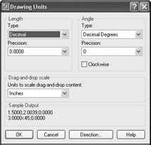
Figure 3.1: The Drawing Units dialog boxYou can also open the Drawing Units dialog box by typing un.
- In the Length area, click the arrow in the Type drop-down list and select Architectural. These units are feet and inches, which you will be using for the cabin project.
Notice the two Precision drop-down lists at the bottom of the Length and Angle areas. When you changed the linear units specification from Decimal to Architectural, the number in the Precision drop-down list on the left changed from 0.0000 to 0'-01⁄16". At this level of precision, linear distances are displayed to the nearest 1⁄16".
- Select some of the other Length unit types from the list and notice the way the units appear in the Sample Output area at the bottom of the dialog box. Then select Architectural again.
Note Drop-down lists are lists of choices with only the selected choice displayed. When you click the arrow, the list opens. When you make another selection, the list closes, and your choice is displayed. You can choose only one item at a time from the list.
- Click the arrow in the Precision drop-down list in the Length area to display the choices of precision for Architectural units (see Figure 3.2). This setting controls the degree of precision to which AutoCAD will display a linear distance. If set to 1⁄16", any line that is drawn more precisely—such as a line 6'-31⁄32" long—is displayed to the nearest 1⁄16" or, in the example, as 6'-31⁄16". But the line will still be 6'-31⁄32" long.
If you change the precision setting to 1⁄32" and then use the Distance command (explained in Chapter 7) to measure the line, you will see that its length is 6'-31⁄32".
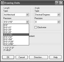
Figure 3.2: The Precision drop-down list for Architectural units - Click 0'-01⁄16" to maintain the precision for display of linear units at 1⁄16".
If you open the Type drop-down list in the Angle area, you see a choice between Decimal Degrees and Deg/Min/Sec, among others. Most drafters find the decimal angular units the most practical, but the default precision setting is to the nearest degree. This might not be accurate enough, so you should change that to the nearest hundredth of a degree.
- Click the arrow in the Precision drop-down list in the Angle area.
- Click 0.00.
The Drawing Units dialog box will now indicate that, in your drawing, you plan to use Architectural units with a precision of 1⁄16" and Decimal angular units with a precision of 0.00 (see Figure 3.3).
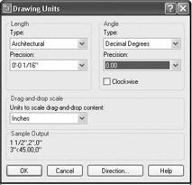
Figure 3.3: The Drawing Units dialog box after changesClicking the Direction button at the bottom of the Drawing Units dialog box opens the Direction Control dialog box that has settings to control the direction of 0 degrees. By default, 0 degrees is to the right—or east—and positive angular displacement goes in the counterclockwise direction. (See Figure 2.7 in Chapter 2 for an explanation of this.) These are the standard settings for most uses of CAD. There is no need to change these from the defaults. If you want to take a look, open the Direction Control dialog box, note the choices, and then click OK to close it. You won’t have occasion in the course of this book to change any of those settings.
Note You will have a chance to work with the Surveyor angular units later in the book, in Chapter 12, when you develop a site plan for the cabin.
- Click OK in the Drawing Units dialog box to close it. Notice the coordinate readout in the lower-left corner of the screen. It now reads out in feet and inches.
This tour of the Drawing Units dialog box has introduced you to the choices you have for the types of units and the degree of precision for linear and angular measurement. The next step in setting up a drawing is to determine its size.
| Note |
If you accidentally click the mouse when the cursor is on a blank part of the drawing area, AutoCAD starts a rectangular window. I’ll talk about these windows soon, but for now, just press the Esc key to close the window. |
Drawing Size
As you discovered earlier, the default drawing area on the screen for a new drawing is 12 to 16 units wide and 9 units high. After changing the units to Architectural, the same drawing area is now 12 to 16 inches wide and 9 inches high.
You can check this by moving the crosshair cursor around on the drawing area and looking at the coordinate readout, as you did in the previous chapter.
| Tip |
When you change Decimal units to Architectural units, one Decimal unit translates to one inch. Some industries, such as civil engineering, often use Decimal units to represent feet instead of inches. If the units in their drawings are switched to Architectural, a distance that was a foot now measures as an inch. To correct this, the entire drawing must be scaled up by a factor of 12. |
The drawing area is defined as the part of the screen in which you draw. You can make the distance across the drawing area larger or smaller through a process known as zooming in or out. To see how this works, you’ll learn about a tool called the grid that helps you to draw and to visualize the size of your drawing.
The Grid
The grid is a pattern of regularly spaced dots used as an aid to drawing. You can set the grid to be visible or invisible. The area covered by the grid depends on a setting called Drawing Limits. To learn how to manipulate the grid size, you’ll make the grid visible, use the Zoom In and Zoom Out commands to vary the view of the grid, and then change the area over which the grid extends by resetting the drawing limits. Before doing this, however, let’s turn off the User Coordinate System icon that currently sits in the lower-left corner of the drawing area. You’ll display it again and learn how to use it in Chapter 8.
- At the Command: prompt, type ucsicon, and then type off. The icon will disappear.
- At the Command: prompt, move the crosshair cursor to the status bar at the bottom of the screen and click the Grid button. The button will appear to have been pushed down, and dots will appear on most of the drawing area (see Figure 3.4). These dots are the grid. They are preset by default to be 1⁄2" apart, and they extend from the 0,0 point (the Origin), out to the right, and up to the coordinate point 1'-0",0'-9". Notice that rows of grid dots run right along the left edge, top, and bottom of the drawing area, but the dots don’t extend all the way to the right side. The grid dot at the 0,0 point is positioned exactly at the lower-left corner of the screen, and the grid at 1'-0",0'-9" is on the top edge, not too far from the upper-right corner.
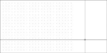
Figure 3.4: The AutoCAD default gridYou can also control the visibility of the UCS icon by choosing View Display UCS Icon On. If On has a check mark, clicking it turns off the UCS icon. If it doesn’t, clicking turns the icon back on.
- For a better view of the entire grid, use the Zoom Out command. From the drop-down menu, choose View Zoom Out. The view changes, and the grid appears smaller (see Figure 3.5). Move the crosshair cursor to the lower-left corner of the grid, and then move it to the upper-right corner. Notice the coordinate readout in the lower left of your screen. These two points should read as approximately 0'-0",0'-0" and 1'-0",0'-9", respectively.
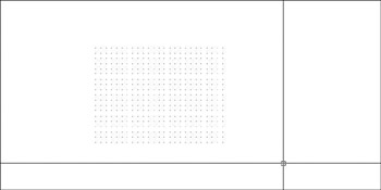
Figure 3.5: The grid after zooming out - On the status bar, next to the Grid button, click the Snap button, and then move the cursor back onto the grid and look at the coordinate readout again. The cursor stops at each grid point, and the readout is to the nearest half inch. Now when you place the crosshair cursor on the lower-left corner of the grid, the readout is exactly 0'-0",0'-0", and 1'-0",0'-9" for the upper-right corner. The Snap tool locks the cursor onto the grid dots, and even when the cursor is not on the grid but somewhere outside it on the drawing area, the cursor maintains the grid spacing and jumps from one location to another.
- Use the Zoom Out command a few more times. The first time, the grid gets even smaller. After the second or third use of the command, the grid may disappear, in which case you see a message on the second line of the Command window that says Grid too dense to display. Once the dots get too close together, AutoCAD lets you know that the monitor can’t display them.
- On the same menu, use the Zoom In tool enough times to bring the view of the grid back to the way it was in Figure 3.5. You are not changing the size of the grid, just the view of it. It’s like switching from a normal to a telephoto lens on a camera.
The grid is more a guide than an actual boundary of your drawing. You can change a setting to force lines to be drawn only in the area covered by the grid, but this is not ordinarily done. For most purposes, you can draw anywhere on the screen. The grid merely serves as a tool for visualizing how your drawing is going to be laid out.
Because it will serve as a layout tool for this project, you need to increase the area covered by the grid from its present size of 1' 9" to 60' 40'. Because the Drawing Limits setting controls the size of the grid, you need to change it.
Drawing Limits
The Drawing Limits setting records the coordinates of the lower-left and upper-right corners of the grid. The coordinates for the lower-left corner are 0,0 by default and are usually left at that setting. You need to change only the coordinates for the upper-right corner.
- At the Command: prompt, choose Format Drawing Limits from the drop-down menu. Notice the Command window:
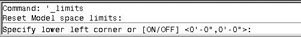
The bottom command line tells you that the first step is to decide whether to change the default X and Y coordinates for the lower-left limits, both of which are currently set at 0',0". There is no need to change these.
- Press to accept the 0',0" coordinates for this corner. The bottom command line changes and now displays the coordinates for the upper-right corner of the limits. This is the setting you want to change.
- Type 60',40'. Be sure to include the foot sign (').
Note AutoCAD requires that, when using Architectural units, you always indicate when a distance is feet by using the foot sign ('). You do not have to use the inch sign (") to indicate inches.
The grid now appears to extend to the top-right edge of the drawing area (see Figure 3.6), but it actually extends way past the edges. It was one foot wide and now it’s 60 times that, but the drawing area is showing us only the first foot or so. To bring the whole grid onto the screen, use the Zoom command again, but this time you will use the All option.
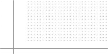
Figure 3.6: The same view with the grid extended to 60' 40' - Choose View Zoom All. The grid disappears, and you get the Grid too dense to display message in the Command window.
Remember that you found the grid spacing to be 1⁄2", by default. If the drawing area is giving us a view of a 60' 40' grid with dots at 1⁄2", the grid is 1440 dots wide and 960 dots high. If the whole grid were to be shown on the screen, the dots would be so close together that they would only be about one pixel in size and would solidly fill the drawing area. So AutoCAD won’t display them at this density. For this reason, you need to change the spacing for the dots.
You need to change the spacing for another reason: for the drawing task ahead, it will be more useful to have the spacing set differently. Remember how we turned Snap on, and the cursor stopped at each dot? If you set the dot spacing to 12", you can use Grid and Snap modes to help you draw the outline of the cabin because the dimensions of the outside wall line are in whole feet: 25' 16'. Here’s how:
- Right-click the Grid button on the status bar, and choose Settings from the small menu that opens. The Drafting Settings dialog box opens, and the Snap And Grid tab is active (see Figure 3.7). The settings in both the Grid and Snap areas include X and Y Spacing settings. Notice that they are all set for a spacing of 1⁄2". The other settings in the dialog box don’t concern us right now.
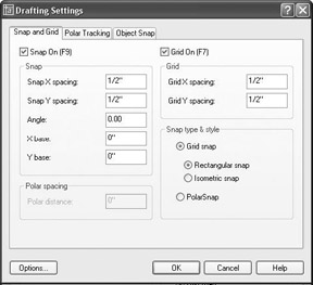
Figure 3.7: The Snap And Grid tab of the Drafting Settings dialog box - In the Grid area, click in the GridX Spacing text box and change the 1⁄2" to 0. If you set the grid spacing to 0, it will then take on whatever spacing you set for the SnapX Spacing text box. This is how you lock the two together. When the GridX Spacing text box reads 0, click the 1⁄2" in the GridY Spacing text box. It changes to match the GridX Spacing text box.
- In the Snap section, change the SnapX Spacing setting to 12. The inch sign is not required. Then click the SnapY Spacing setting. It automatically changes to match the SnapX Spacing and changes both text boxes to display as 1' instead of 12".
- In the Snap Type & Style area, be sure Grid Snap and Rectangular Snap are selected. The Snap On and Grid On check boxes at the top of the dialog box should be checked. If they aren’t, click them.
- Click OK. The grid is now visible (see Figure 3.8). Move the cursor around on the grid—be sure Snap is on. (Check the Snap button on the status bar. It will be pressed when Snap is on.) Notice the coordinate readout. It is displaying coordinates to the nearest foot to conform to the new grid and snap spacing.
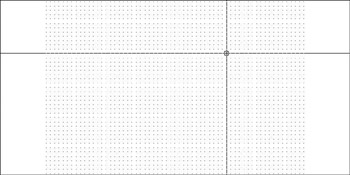
Figure 3.8: The new 60' 40' grid with 12" dot spacing - Move the crosshair cursor to the upper-right corner of the grid and check the coordinate readout. It should display 60'-0", 40'-0", 0'-0". (In LT, you won’t have the third coordinate.)
Drawing with Grid and Snap
Your drawing area now has the proper settings and is zoomed to a convenient magnification. You should be ready to draw the first lines of the cabin.
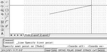
- At the Command: prompt, start the Line command. (Click the Line button on the Draw toolbar.) Pick a point on the grid in the lower-left quadrant of the drawing area (see Figure 3.9).
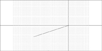
Figure 3.9: One point picked on the grid - Hold the crosshair cursor to the right of the point just picked, and look at the coordinate readout. It may be displaying relative polar coordinates from the first point picked, but probably not. If it isn’t, try clicking once on the coordinate readout. If that doesn’t work, clicking one more time will do the job, because a three-way toggle controls the coordinate readout.
- Now hold the crosshair cursor directly out to the right of the first point picked, and look at the coordinate readout. It will be displaying a distance in whole feet and should have an angle of 0.00. (For AutoCAD users, ignore the extra Z coordinate.)
- Continue moving the crosshair cursor left or right until the readout displays 25'-0"<0.00. At this point, click the left mouse button to draw the first line of the cabin wall (see Figure 3.10).
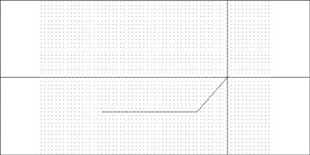
Figure 3.10: The first line of the cabin wall is drawn. - Move the crosshair cursor directly above the last point picked to a position such that the coordinate readout displays 16'-0"<90.00, and pick that point.
- Move the crosshair cursor directly left of the last point picked until the coordinate readout displays 25'-0"<180.00, and pick that point (see Figure 3.11).
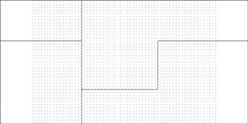
Figure 3.11: Drawing the second and third wall lines - Finally, type c to close the box. This tells AutoCAD to draw a line from the last point picked to the first point picked and, in effect, closes the box. AutoCAD then automatically ends the Line command (see Figure 3.12).
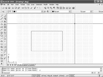
Figure 3.12: The completed outside wall lines
This method for laying out building lines by using Snap and Grid and the coordinate readout is quite useful if the dimensions all conform to a convenient rounded-off number, such as the nearest 6 inches or, as in this case, the nearest foot. It is not necessary to keep Snap and Grid set to the same spacing, as they were in this example, as long as the grid spacing is a whole multiple of the snap spacing. In this project, you could have kept the snap spacing at 1' and set the grid spacing to 4'. You then wouldn’t have so many dots on the screen, and Snap would still have forced the crosshair cursor to stop at quarter intervals (every 12") between the 4-foot–spaced grid dots. This would have been a slightly more elegant way to accomplish the same thing.
The key advantage to this method over just typing the relative coordinates—as was done with the box in Chapter 2—is that you avoid having to type the numbers. You should, however, assess whether the layout you need to draw has characteristics that lend themselves to using Grid, Snap, and the coordinate readout area or whether just typing the relative coordinates would be more efficient. As you get more comfortable with AutoCAD, you will see that this is the sort of question that comes up often: which way is the most efficient? This happy dilemma is inevitable in an application with enough tools to give you many strategic choices. In Chapters 4 and 5, you will learn other techniques for drawing rectangles.
Saving Your Work
As with all Windows-compatible applications, when you save a file for the first time by choosing File Save, you can designate a name for the file and a folder in which to store it. Normally, you use Windows Explorer to designate file and folder information before you start a new drawing; but for the cabin project, you will do that now, after the drawing has been started.
I recommend that you create a special folder, called something like Training Data, for storing the files you will generate as you work your way through this book. This will keep them separate from project work already on your computer, and you will always know where to save or find a training drawing. To save your drawing, follow these steps.
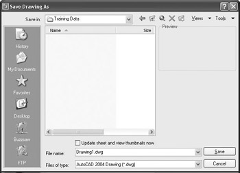
- In AutoCAD, click the Save button on the Standard toolbar or choose File Save. Because you haven’t named this file yet, the Save Drawing As dialog box opens.
Note The actual folders and files may be different on your computer.
- In the Save In drop-down list, designate the drive and folder where you want to save the drawing. If you are saving it on the hard drive or server, navigate to the folder in which you want to place the new Training Data folder.
- Click the Create New Folder button near the top-right corner of the dialog box. The folder appears in the list of folders. It is called New Folder. Right-click the new folder and choose Rename from the shortcut menu that opens.
- Enter Training Data (or whatever name you want to give the new folder) .
- Double-click the new folder to open it.
- In the File Name box, change the name to Cabin03. You’re not required to enter the .dwg extension in this case.
From now on, when you are directed to save the drawing, save it as Cabinx, with x indicating the number of the chapter. This way, you will know where in the book to look for review, if necessary. Name multiple saves within a chapter Cabinxa, Cabinxb, and so on.
- Click Save. Notice that the title bar now displays the new name of the file along with its path. It is now safe to exit AutoCAD.
- If you want to shut down AutoCAD at this time, choose File Exit. Otherwise, keep your drawing up and read on.
The tools covered in this chapter will be your key to starting a new drawing from scratch and getting it ready for a specific project.
Using the Wizard to Set Up a New Drawing
AutoCAD comes with two Setup wizards, Quick and Advanced. Neither helps you set up Grid and Snap, but they do help you with setting the Units and the Drawing Limits. Here is a summary of how the wizards work.
When you select Use A Wizard in the Startup dialog box, you are prompted to choose Quick or Advanced.
The Quick Wizard
- Units: Select Units, and then click the Next button.
- Area: Here you set the Drawing Limits by specifying the X and Y coordinates of the upper-right corner. You do this by entering the x value for the Width, and the y value for the Length. For example, if the coordinates of the upper-right corner are 60', 40' as they are for the cabin drawing, enter 60' for the width and 40' for the length. Then click Finish.
- Now you will need to Zoom to All, and specify your Grid and Snap settings. They stay at the default setting of 1⁄2", and both remain off. Use the procedure shown in this chapter.
The Advanced Wizard
- Units: Select the Linear Units and the Precision. Then click Next.
- Angle: Select the Angular Units and the Precision. Then click Next.
- Angle Measure: Ignore this and click the Next button.
- Angle Direction: Ignore this and click the Next button.
- Area: Here you set the Drawing Limits by specifying the X and Y coordinates of the upper-right corner. You do this by entering the x value for the Width and the y value for the Length. For example, if the coordinates of the upper-right corner are 60', 40' as they are for the cabin drawing, enter 60' for the Width and 40' for the Length. Then click Finish.
- Now you will need to Zoom to All, and specify your Grid and Snap settings, as they stay at the default setting of 1⁄2", and both remain off. Use the procedure shown in this chapter.
A Summary of AutoCAD s Units
The following is a brief description of each of the linear and angular unit types that AutoCAD offers the user and how they are used. The example distance is 2'-61⁄2". The example angle is 12635'10".
Linear Units
The linear unit types that AutoCAD uses are as follows:
ArchitecturalThis unit type uses feet and inches with fractions. You must use the foot sign ('), for example, 2'-61⁄2". For this distance, enter 2'6-1⁄2 or 2'6.5. For the most part, these are the units that will be used in this book.
DecimalUses decimal units that can represent any linear unit of measurement. You do not use the foot sign, the inch sign, or fractions. For example, if each decimal unit equals 1 inch, to specify a line to be 2'-61⁄2" long, you must convert feet to inches and enter a length of 30.5. But if each decimal unit equals 1 foot, you must convert the inches to the decimal equivalent of a foot and enter 2.5417.
EngineeringThis unit is equivalent to Architectural units except that inches are displayed as decimals rather than fractions. For a distance of 2'-61⁄2", enter 2'6.5 or 2.5417'. In either method, the resulting distance will be displayed as 2-6.5".
FractionalThese units are just like Architectural units except there is no use of feet. Everything is expressed in inches and fractions. If you enter 30-1⁄2 or 30.5, the resulting distance displays as 301⁄2.
ScientificThis unit system is similar to the Decimal unit system except for the way in which distances are displayed. If you enter 3.05E+01, that is what is displayed. The notation always uses an expression that indicates a number from 1 to 10 that is to be multiplied by a power of 10. In this case, the power is 1, so the notation means 3.05 10 or 30.5 in Decimal units.
Angular Units
The angular unit types that AutoCAD uses are as follows:
DecimalThis type uses 360 degrees in a circle in decimal form, with no minutes and no seconds. All angles are expressed as decimal degrees. For example, an angle of 12635'10" is entered as 126.586 or 126d35'1" and displays as 126.5861. AutoCAD uses a d instead of the traditional degree symbol ().
Deg/Min/SecThis is the traditional system for measuring angles. In AutoCAD’s notation, degrees are indicated by the lowercase d, the minutes use the traditional ', and the seconds use the traditional ". The system is clumsy. Most users now use decimal angles instead of this system and choose their preference for precision.
GradsThis unit is based on a circle being divided into 400 grads, so 90 equals 100 grads. One degree equals 1.11 grads, and 1 grad equals 0.90 degrees. AutoCAD uses g as the symbol for grads.
RadiansThe radian is the angle from the center of a circle made by the radius of the circle being laid along the circumference of the circle. One radian equals 57.3 degrees, and 360 degrees equals 6.28 radians or 2p radians. AutoCAD uses r as the symbol for radians.
SurveyorThese units use bearings from the north and south directions, toward the east or west directions, and are expressed in degrees, minutes, and seconds. They will be discussed in Chapter 12. In the example we are using, 126 35' 10" translates to N 36d35'10" W in bearings, or Surveyor units.
The next chapter will focus on adding to the drawing, modifying commands you learned as part of Chapter 2, and creating strategies for solving problems that occur in the development of a floor plan.
If You Would Like More Practice
Set up a few more new drawings. Use parameters that you might use in your own profession if it isn’t architecture. Following are three practice setup challenges and a summary of steps described in this chapter. Use this procedure, or feel free to try the Use A Wizard options in the Startup dialog box.
|
Architecture Project: |
Building size: |
125' 85' |
|
Units: |
Architectural |
|
|
Drawing Limits: |
200', 150' |
|
|
Grid/Snap Spacing: |
5' |
|
|
Civil Project: |
Building Size: |
87' 60' |
|
Units: |
Decimal |
|
|
Drawing Limits: |
120', 90' |
|
|
Grid/Snap Spacing: |
10' |
|
|
Mechanical Project: |
Block Size: |
6" 10" |
|
Units: |
Decimal |
|
|
Drawing Limits: |
1' 2' |
|
|
Grid/Snap Spacing: |
1" |
Summary of the procedure:
- Set the units.
- Set the drawing limits.
- Set Grid Spacing to 0, and set Snap Spacing to the given distance.
- Turn on Grid and Snap.
- Zoom to All.
- Draw the rectangle using relative Cartesian or polar coordinates.
Are You Experienced?
Now you can
- set up linear and angular units for a new drawing
- make the grid visible and modify its coverage
- use the Zoom In and Zoom Out features
- activate the Snap mode and change the Snap and Grid spacings
- use the Zoom All function to fit the grid on the drawing area
- draw lines using Grid, Snap, and the coordinate readout
- create a new folder on your hard drive from within AutoCAD
- name and save your file
Introduction
- Getting to Know AutoCAD
- Basic Commands to Get Started
- Setting Up a Drawing
- Gaining Drawing Strategies: Part 1
- Gaining Drawing Strategies: Part 2
- Using Layers to Organize Your Drawing
- Grouping Objects into Blocks
- Generating Elevations
- Working with Hatches and Fills
- Controlling Text in a Drawing
- Dimensioning a Drawing
- Managing External References
- Using Layouts to Set Up a Print
- Printing an AutoCAD Drawing
- Appendix A Look at Drawing in 3D
EAN: N/A
Pages: 159
