VERTEX AND PIXEL SHADERS
|
|
There are a variety of techniques that require processing by both vertex and pixel shaders. This is the most common technique for shader usage.
Cartoon Shading
Cartoon shading is just trying to get an object shaded as though it were drawn in the comic book style. It's typified by a simple two or three color shading scheme, occasionally with an emphasized object outline.
Uses This technique allows you to specify the color of an object based upon lighting calculations, allowing you to specify the number of shading contours, where the contours occur according to the shading level and the color of the contours.
Description This technique uses a vertex shader to calculate the n • l value and to pass that value into the pixel shader as a texture coordinate. In this example, we do not use the texture coordinate to sample a texture—no textures are loaded, we just use the texture coordinates as an indication of how illuminated the pixel is and then choose the color based upon that value.
Prerequisites Object contour colors and thresholds are set in the pixel shader as constants. v0 is the vertex position; the normal is passed in as v3.
Results This shader uses a Lambertian calculation to compute the diffuse lighting intensity and passes that value to the pixel shader though a texture register. The output is shown in Figure 7.16.
// Real - Time Shader Programming // toon shader.vsh // calculation in the pixel shader. // Pass out the normal, light and half angle vectors in eye // space coordinates in three texture coordinates. vs.1.1 // transform the vertex m4x4 oPos, v0, c[TRANS_MVP] // compute the normal in eye space m3x3 rO, v1, c[MV_MATRIX] mov oTO, r0 // write the normal to tex coord 0 // compute the light vector sub r0, c[LIGHT_POS], v0 dp3 r1, r0, r0 rsq r1, r1 mul r0, rO, r1 // r0 = |1| // transform the light vector into eye space m3x3 r1, r0, c[MV_MATRIX] mov oT1, r1 // write the light vector to tex coord 1 // compute half vector // transform the vertex position into eye space m4x4 r0, v0, c[MV_MATRIX] dp3 r3, r0, r0 // normalize to get the view vector rsq r3, r3 mul r0, r0, r3 // r0 = |v| add r0, r1, -r0 // add the light vector and the view vector = half angle dp3 r3, r0, r0 // normalize the half angle vector rsq r3, r3 mul r0, r0, r3 // r0 = |h| // write the half angle vector to tex coord 2 mov oT2, r0
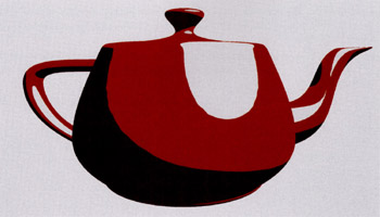
Figure 7.16: Cartoon shading using traditional lighting equations and a three-stage color graduation.
This shader computes the light intensity as n • l and places it in texture 0's u component. The next step can be done in a number of ways. You could load the shading gradient you want in a 1D texture as texture 0 and use that without a pixel shader. Or you can use the opportunity to code a pixel shader and let the shader code determine the colors. You can then load the colors and contour control values or do what we've done here, program them directly into the pixel shader.
// toon shader.psh ps.1.4 // get the normal in rO texcrd rO.xyz, tO // get the light vector r1 texcrd r1.xyz, t1 // get the half angle vector in r2 texcrd r2.xyz, t2 // r3 = n dot 1 dp3 r3, rO, r1 // subtract cutoff1 from n dot 1 sub r3, r3, cO // if greater than zero use lit color (c3) otherwise // use the unlit (c2) // store result in r5 cmp_sat r5, r3, c3, c2 // r4 = n dot h dp3 r4, rO, r2 // subtract cutoff2 from n dot h sub r4, r4, c1 // if greater than zero use specular color (c4) // otherwise previous color // store result in output register r0 cmp_sat r0, r4, c4, r5
Dot-3 Bump Mapping
Dot-3 bump mapping is the most commonly used style of bump mapping. It uses a texture called the normal map to store the bump textures. Instead of rgb values, these are the actual xyz normal perturbations that are going to be applied on the surface. In previous versions of DirectX, this was supported directly by the D3DTOP_DOTPRODUCT3 blending operation.
Uses This shader demonstrates how to create a dot-3 bump mapping.
Description Takes a normal map texture and modulates the diffuse color texture map by the dot product of the light vector and the normal vector.
Prerequisites v0 is the vertex position; the normal is passed in as v3. The textures are the same ones used in the multitexture shader.
Results The result of the shader is shown in Figure 7.17.
// Dot - 3 Bump.vsh vs.1.0 // Shader version 1.0 // emit transformed position m4x4 oPos, v0, c[TRANS_MVP] // Transform normal and tangent m3x3 r7,v8,c0 m3x3 r8,v3,c0 // Cross product mul r0,-r7.zxyw,r8.yzxw; mad r5, -r7.yzxw,r8.zxyw,-r0; // Transform the light vector dp3 r6.x,r7,-c16 dp3 r6.y,r5,-c16 dp3 r6.z,r8,-c16 // Multiply by a half to bias, then add half mad r6.xyz,r6.xyz,c20,c20 mov oT0.xy,v7.xy mov oT1.xy,v7.xy mov oDO.xyz,r6.xyz
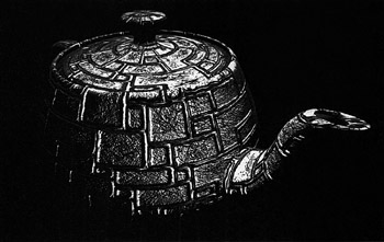
Figure 7.17: Taking a bump map to generate normal perturbations that look like real geometry except at the edges of the object.
The pixel shader reads in the texture map and the normal map. The normal is passed in as the v0 register, and then it's used with the light vector to generate a dot product. The dot product is then used to modulate the base texture.
// Dot - 3 Bump.psh ps.1.1 // Shader version 1.1 tex t0 // Sample texture tex t1 // Sample normal mov r0.t1 dp3 r0,t1_bx2,v0_bx2; // Dot(light,normal) mul r0,t0,r0 // Modulate against base color
Fresnel Shader
This technique comes from the DirectX Shader Workshop from Meltdown 2002. It approximates the Fresnel term by computing the term as
![]()
which is done in the shader rather than through a texture lookup. This shader gives a simulation of the Fresnel edge effect.
Uses Use this shader to add a simulated Fresnel term with minimal effort.
Description This shader computes an edge effect. It can be added to an existing shader to generate something that looks like a Fresnel effect. It uses the dot product of the view direction with the vertex normal to add in a specified color.
Prerequisites v0 is the vertex position; the normal is passed in as v3. In addition to the MVP matrix, we'll need the MV matrix and an eye position input as constants.
Results The Fresnel shader effect is shown in Figure 7.18. Figure 7.19 shows the Fresnel shader used with a diffuse and specular shader.
// Fresnel . vsh vs.1.0 // Shader version 1.0 // emit transformed position m4x4 oPos, v0, c[TRANS_MVP] // Transform position and normal to world space m4x4 r0, v0, c[TRANS_M] m3x3 r1, v3, c[TRANS_M] // Compute normalized view vector add r0, -r0, c[EYE_POS] // vector dp3 r0.w, r0.xyz, r0.xyz rsq r0.w, r0.w mul r0, r0, r0.w // r0 = |v| // Compute e dot n dp3 r0, r0, r1; // compute the color complement add r0, c[COLOR], -r0 // cube the value mul r1, r0, r0 mul r0, r1, r1 // multiply by Fresnel and place in output mul 0D0, r0, c[FRESNEL]
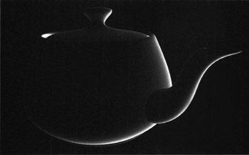
Figure 7.18: A simplified Fresnel shader used to generate a shiny specular when an object is illuminated from behind.
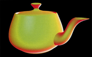
Figure 7.19: The Fresnel shader output added to the ambient, diffuse, and specular output.
|
|
EAN: 2147483647
Pages: 104