IPSec Tunnel Termination Redundancy
| The IPSec HA design in Figure 5-3 eliminates all single points of failure between the two tunnel termination points of the IPSec VPN except onethe tunnel termination point itself. Indeed, all of the network topologies discussed up to this point present single points of failure at the actual tunnel termination point itself. In this section, we will discuss three methods for designing HA into the termination of the IPSec VPN tunnel:
In addition to these tunnel termination redundancy methods, redundancy can be built into the IPSec VPN tunnel infrastructure between the termination points of the IPSec VPN tunnel. The availability of the routing protocol that provides the underlying transport between IPSec VPN tunnel termination points therefore has a material impact on the system-level IPSec VPN HA. Multiple Physical Interface HA with Highly Available Tunnel Termination InterfacesNow that redundancy has effectively been built into the path between the two tunnel termination points of the IPSec VPN tunnel (Figure 5-3), what happens when a failure occurs on one of the actual IPSec tunnel termination points themselves? All of the extra funding invested in path HA would be negated by such a failure. Figure 5-4 extends the design depicted in Figure 5-3 to include termination-point redundancy using high-available loopback interfaces. Figure 5-4. Tunnel Termination on Highly Available Interfaces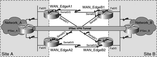 The design illustrated in Figure 5-4 extends path HA to the tunnel termination point itself by utilizing a secondary Fast Ethernet port on the VPN gateways, IPSec_A and IPSec_B. Cisco IOS allows the administrator to source the IPSec VPN tunnel from a loopback interface on IPSec_A and IPSec_B, effectively allowing the two VPN gateways to maintain the IPSec VPN tunnel independently of a failure on one of the two Fast Ethernet interfaces on the box. Likewise, the target termination points are loopback interfaces, allowing for tunnel termination point HA on both the origination and termination sides of the IPSec tunnel. Tunnel Termination HA Using HSRP/VRRP Virtual InterfacesUsing loopback interfaces to terminate the IPSec VPN tunnel, as displayed in Figure 5-4, allows the VPN gateways to leverage redundant interfaces (Fa0/0 and Fa0/1) on IPSec_A and IPSec_B for increased HA. However, this solution does not provide redundancy in a scenario in which the gateway itself fails. To design for box-level tunnel termination point redundancy, HSRP/VRRP virtual interfaces can be used to originate and terminate the IPSec VPN tunnel. Figure 5-5 presents an extension of Figure 5-3 that includes box-level tunnel termination HA using an HSRP Virtual Interface. Figure 5-5. Tunnel Termination Point HA Using HSRP Virtual Interfaces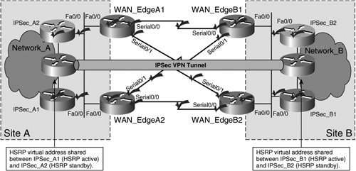 The design illustrated in Figure 5-5 allows for a greater scope of tunnel termination redundancy. Not only does it eliminate the termination interface itself as a single point of failure, but it also eliminates the VPN gateway itself as a single point of failure. For example, if IPSec_A1 were to experience a total system failure due to, say, a power failure in the building, IPSec_A2 would take over as the IPSec VPN tunnel termination point, thereby preserving the consistency of the IPSec VPN. This type of design has two variations:
Note The details of stateful and stateless IPSec HA design between routers in an HSRP group, including configuration, failover operations, and steps to minimize reconvergence delay impact, are discussed in greater detail in Chapter 6, "Site-to-Site Local HA Solutions." HA with Multiple Peer StatementsIn many cases, such as in situations in which geographic IPSec HA is required, it may not be feasible to terminate an IPSec tunnel on a virtual interface using HSRP and/or VRRP. Figure 5-6 depicts an example of one such situation. Figure 5-6. Geographic IPSec HA Using Multiple Peering Statements in Each Crypto Map on IPSec_A1, A2, B1, and B2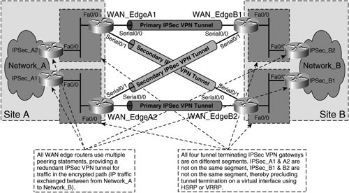 In Figure 5-6, IPSec_A1 and IPSec_A2 are now located in different wiring closets, and therefore do share the same Layer 3 boundary facing the WAN edge routers (WAN_EdgeA1 and WAN_EdgeA2). The same conditions exist at site B for routers IPSec_B1 and IPSec_B2. As such, HSRP or VRRP hellos cannot be sent between IPSec_A1 and A2 or between IPSec_B1 and B2 for IPSec tunnel termination on a virtual interface. In this situation, multiple peering statements can be included in the crypto maps for routers IPSec_A1, A2, B1, and B2, creating a backup IPSec VPN tunnel for encrypted traffic on egress from each IPSec VPN gateway. Figure 5-7 shows the loopback-to-loopback IPSec peering sessions between IPSec_A1, A2, B1, and B2 using redundant peering statements to protect traffic from Network_A to Network_B in the encrypted path. Figure 5-7. Loopback-to-Loopback IPSec Peering Sessions with Redundant Peer Statements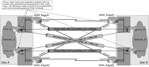 Note Further explanation of design considerations and configuration of sourcing and terminating IPSec tunnels on loopback interfaces can be found in Chapter 6, "Site-to-Site Local HA Solutions." More detail on IPSec VPN design with redundant IPSec peering statements can be found in Chapter 7, "Site-to-Site Geographic HA Solutions." RP-based IPSec HABecause IPSec itself is a Layer 3 VPN technology, IPSec is dependent on the existence of a stable IP transport between tunnel termination points to operate effectively. This means that IPSec requires accurate and timely updating of routing information on intermediate nodes between the termination points of the IPSec tunnel. The routing protocol of the IP infrastructure underneath the IPSec tunnel is responsible for communicating routing information to nodes in between the IPSec tunnel termination endpoints. If there is an RP failure between the two termination points of the IPSec tunnel, then IPSec traffic will not be able to flow between the two endpoints, eventually leading to expiration of the previously negotiated SA lifetimes or timeout of the IKE keepalives (if enabled). Fortunately, IPSec is not path-discriminateIPSec traffic will take any available Layer 3 path from the tunnel source to tunnel destination before tearing down the tunnel. Administrators can therefore leverage the use of routing protocols between tunnel endpoints to provide numerous routed paths between source and destination. Figure 5-8 illustrates a design in which the dedicated WAN circuits incorporated into the designs in Figures 5-1 through 5-7 are replaced with uplinks to an ISP, presenting a much higher degree of HA beyond the interface of the WAN_Edge routers. The ISP has many different paths through which to route packets between the WAN_Edge routers as opposed to just one with the dedicated WAN circuits. Figure 5-8. RP-Based HA between IPSec Tunnel Termination Points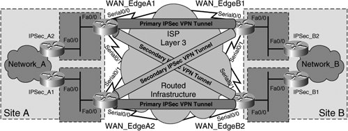 Therefore, by replacing the dedicated WAN circuits between the WAN_Edge routers with dual uplinks on each router to an ISP, the design in Figure 5-8 affords the IPSec VPN a much greater degree of RP-based HA, since the number of Layer 3 paths between endpoints has been greatly expanded. Furthermore, through the use of dual uplinks to the ISP, the design makes no concession in interface-level or box-level IPSec HA. In fact, the design in Figure 5-8 can use the same loopback-to-loopback peering model with redundant peering statements on each IPSec VPN gateway illustrated in Figure 5-7. The change in transport from dedicated WAN circuits to dual uplinks to the ISP on each gateway, while providing greater HA to the IPSec VPN itself, does not necessarily change the peering model of the IPSec VPN itself. Warning You may have noticed already that, as with most value-added services, increased HA usually comes with increased cost. In the context of the design illustrated in Figure 5-5, this cost is represented by the doubling of fee-based WAN links on the WAN_Edge routers (8 ISP uplinks versus 4 dedicated WAN circuits). Because of this, investing in increased HA is a business decision, and the needs of the business should be carefully evaluated when investing in the increased benefit of added IPSec HA. If overlooked, administrators face the risks associated with over-designed IPSec deployments, including increased maintenance, management, complexity, and costs. |
EAN: 2147483647
Pages: 113
- The Second Wave ERP Market: An Australian Viewpoint
- Enterprise Application Integration: New Solutions for a Solved Problem or a Challenging Research Field?
- The Effects of an Enterprise Resource Planning System (ERP) Implementation on Job Characteristics – A Study using the Hackman and Oldham Job Characteristics Model
- Healthcare Information: From Administrative to Practice Databases
- A Hybrid Clustering Technique to Improve Patient Data Quality