Chapter 13: Introduction to Modeling with MilkShape
![]() Download CD Content
Download CD Content
In this and the following chapters, we will be delving into the world of low-poly modeling. We'll talk about techniques and methods that can be applied to other tools, such as the expensive 3D Max or Maya, but the practical focus will be geared toward using MilkShape, UVMapper, and other low-cost tools that are included on the enclosed CD.
MilkShape 3D
In Chapter 9 we created a skin for a simple soup can—remember that? Well, in this chapter we're going to create the model and skin it with the texture you created earlier, only this time we will go beyond just the simple soup can. But first, let's start at the beginning and learn a bit about MilkShape.
MilkShape 3D is a great low-cost low-poly 3D modeling tool created by a fellow named Mete Ciragan. Like most successful shareware applications, it has evolved over the years, as Mete added features requested by his user community. He also added the capability for users to create their own plug-ins to provide additional features and import-export filters.
MilkShape is not as complex as the more expensive tools, but that does not in any way imply that it is not a capable program, especially in the low-poly world that computer games inhabit. In fact, the stripped-down nature of MilkShape certainly makes it easier to learn than most of the "big boys."
Installing MilkShape 3D
If you want to install only MilkShape 3D from the enclosed CD, do the following:
-
Browse to your CD in the \MS3D directory. (MS3D is the abbreviated form for MilkShape 3D. You'll encounter it a fair bit.)
-
Locate the Setup.exe file and double-click it to run it.
-
Click the Next button for the Welcome screen.
-
Follow the various screens and take the default options for each one, unless you know you have a specific reason to do otherwise.
| Note | MilkShape does not know how to open its own files when you double-click them to be launched from Windows Explorer. You need to launch MilkShape first and then browse for your files with the MilkShape File, Open dialog box. |
The MilkShape 3D GUI
| Tip | If you only have three views in your window when you first run MilkShape, choose Window, View ports, 4 Window, and you should get something close to what you see in Figure 13.1. In Figure 13.1 there are four places where the model can be seen. Each of these is what MilkShape calls a window. We will call them frames in this book, because as you probably already know, Milk Shape itself is in a window. A view is the angle or direction at which you look at an object. For example, if you stand in front of an object and look at it, you are seeing the front view. From above, it is the top view. A viewport is the little frame inside the MilkShape window in which a view of a model is presented. When I want to direct your attention to a particular viewport, I might refer to it as being in a particular frame. MilkShape calls these frames windows, which is a bit of a misnomer. For example, in Figure 13.1 the 3D view is in the 3D viewport, located in the lower-right frame in the MilkShape window. |
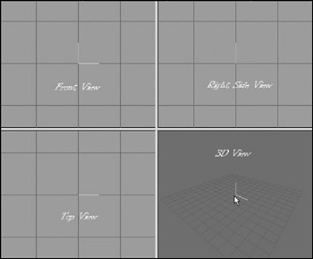
You'll notice in Figure 13.1 that I've labeled the different views. This is the way you should use your views for models that you create for Torque. Other applications and games may require your models to be oriented differently.
Three of the views are wire-frame-only views; they allow you to look at your model from directly above, directly in front, and the right-hand side. The fourth view is a 3D view in which you can rotate your model various different ways and view it as a wire-frame, shaded, or fully textured model with lighting cues.
Figure 13.2 shows the tools available in the toolbox section. Although some tools for different operations are only available in the menus, most of the time you will be working with the tools in the toolbox.
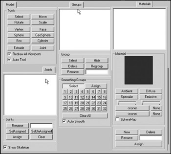
Figure 13.2: The toolbox contents.
Navigating in Views
In the wire-frame views, you can move the view around by holding down the Ctrl key and clicking and dragging in the window.
If you hold down the Shift key and drag the mouse, you can zoom in or out. Be careful though—if you are in select mode (from the Model tab), the program will alternate between zooming and object-selecting each time you press the Shift key and drag the mouse button. With practice you can master this and it will become quite useful. This behavior only occurs in select mode. In all other modes, the shift-drag action will always zoom the view in or out with no alternation.
If you have a wheel mouse, then the wheel can be used to zoom in or out. You will have to click in the view to get focus into the view before the zoom will work.
The 3D view allows the view movement in the same ways as the other views, except the wheel mouse zoom works backward.
View Scale and Orientation
When you are viewing an object from the front in MilkShape, the Y-axis is positive going up, the X-axis is positive going to the right, and the Z-axis is positive going to the front. This makes it a right-handed coordinate system.
If you look at the Right Side view (the view at the upper right of the four), you will see in the center the axis "bugs" for the Y- and Z-axes. Although it is not visible in the black-and-white pictures in this book, the Y-axis line is cyan and the Z-axis line is magenta. The place where these two lines meet is the (0,0,0) coordinate in object space. Hold your mouse cursor over the first grid line above the (0,0,0) location and look down to the lower-left corner of the MilkShape window while keeping your cursor over that grid line. You should see the Y-axis value at about 20.0 or so (see Figure 13.3). If you see 20.005 or 19.885, that's good enough. If you don't see 20.0 or so, zoom the view in or out until you do. Adjust your other two wire-frame views to the same scale. If you position your cursor one grid line directly above the (0,0,0) point on the Front view (upper left), you should see the 20.0 or so also for the Y value, but for the Top view, the same relative positioning will be affected in the Z-axis.
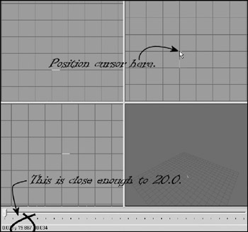
Figure 13.3: Checking the zoom in the Right Side view.
Figure 13.4 contains various notations to help you understand the coordinate display system. In this figure, I've left in MilkShape's viewport labels above each viewport's frame in order to illustrate the variation that emerges with the Torque Right Side view being seen in MilkShape's Left viewport.
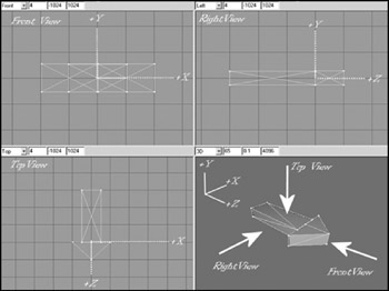
Figure 13.4: Torque-oriented object in the MilkShape viewports.
The whole point of this little exercise is to expose you to the coordinate display and to ensure that your layout matches the one we'll be working with here. Of course, at times when you zoom in and out this might change, but now you have a method of recalibrating when necessary.
The Soup Can Revisited
Now that you have a bit of a grasp of what you are looking at in the GUI, and how to move your views around to look at your model, we'll move on to actually creating a quick model to get your feet wet. There's nothing like doing for learning!
Creating the Basic Shape
A closed can is a cylinder. A cylinder is what we call a primitive shape, like a sphere or a cube. The primitives are added together in various ways to build up more complex shapes.
-
Choose the Model tab in the toolbox.
-
Click on Cylinder.
-
Position your cursor in the Right Side view about three grid lines above (0,0,0) and one grid line to the left. Click and drag down and to the right until your object looks like Figure 13.5.
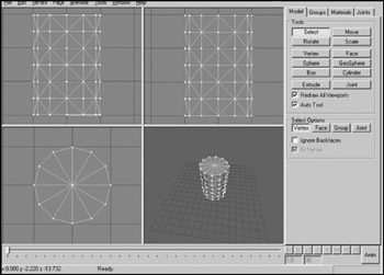
Figure 13.5: Making a cylinder. -
Choose the Groups tab. You will see a single group named cylinder01 (it may be a higher number if you made more cylinders and deleted them—MilkShape just adds 1 to the number at the end during its auto-naming).
Tip You may recall encountering the term mesh way back in Chapter 3. In MilkShape the word group is actually an analogue for the word mesh. They mean essentially the same thing.
-
Click on the group name to highlight it, and then type can in the box to the right of the Rename button where it says "Cylinder01".
-
Click Rename, and the group will now be called can.
-
Choose the Materials tab.
-
Click New.
-
Type label into the Materials Rename box.
-
Click Rename.
-
In the Material frame of the Materials tab you will see two buttons labeled "<none>". These are the texture buttons. The top one assigns the standard texture, and the bottom one allows you to assign a texture whose alpha channel you want to use for this material.
-
Click the top texture button. You will get a file dialog box.
-
Browse your way to C:\3DGPAi1\resources\ch9 and double-click the
 can.jpg file.
 -
Now choose the Groups tab again, make sure your cylinder's group is selected in the list. If your can is not already highlighted in red, click Select. You will see your can highlighted in red in the three wire-frame views.
-
While your can is still selected, switch back to the Materials tab, choose your new material in the list, and click Assign.
Tip If your screen resolution is set to 800 600 or less, you will not be able to see the entire Assign or Select By buttons.The top one-quarter or so of those buttons is just visible on the bottom-right corner. Assign is located below the Rename button, and Select By is located below the edit box that is to the right of the Rename button.
-
Right-click in the 3D view and choose Textured. Your can should appear with the texture wrapped around it, like in Figure 13.6.
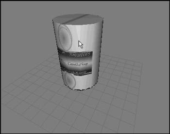
Figure 13.6: Assigned texture. -
Save your work so far as mynewcan.ms3d somewhere, by choosing File, Save As.
-
In preparation for UV unwrapping the can object, choose File, Export, Wavefront Obj and export the file to C:\3DGPAi1\resources\ch9\mynewcan.obj.
Okay, so we have the soup can made, and we've assigned the texture to it. The reason the texture doesn't fit right yet is because the texture coordinates haven't been mapped to the object yet. That's our next step.
UV Unwrapping the Can
In Chapter 9 we encountered some of the theory and process behind UV unwrapping and mapping. In a later section in this chapter we'll go into more theory, as well as more detail about the UVMapper tool. For our purposes at the moment, we just want to get the texture skin mapped correctly onto the can.
Whether the skins are created before the object or the object is created first will probably change from project to project or even from phase to phase within a project. At this point in the book, we already have a skin—can.jpg—so we want to make sure the can will unwrap to match the skin. This isn't a problem in this case. It may be a problem with other projects though, so be aware of that possibility.
-
Using Windows Explorer, browse your way to C:\3DGPAi1\resources\tools and launch
UVMapper.exe. -
Maximize the window when it opens.
-
Find the file you exported, C:\3DGPAi1\resources\ch9\mynewcan.obj, and open it.
-
You will see an alert, listing some statistics about the object. Click OK.
-
You will see a bunch of triangles fill your window. Ignore them for the moment.
-
Choose Edit, New UV Map, Cylindrical Cap. You will get a Cylindrical Cap Mapping dialog box.
-
Click OK. You will then get a layout of the can's triangles (like that in Figure 13.7), with a rectangular block of triangles across the middle and a circle of triangles at both top and bottom.
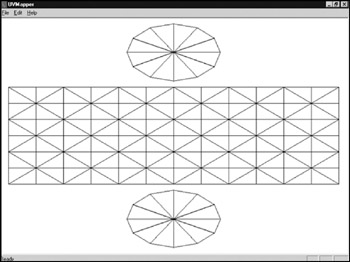
Figure 13.7: Unwrapping the can in UVMapper. -
Choose File, Save Model. The OBJ Export Options dialog box then appears.
-
Set the options boxes as shown in Table 13.1 and click OK.
Table 13.1: UVMapper OBJ Export Options Values Value
Option
clear
Export As Single Group
set
Export Normals
set
Export UV Coordinates
clear
Flip Texture (UV) Coordinates Vertically
clear
Flip Texture (UV) Coordinates Horizontally
clear
Reverse Winding Order
clear
Invert Normals
clear
Swap Coordinates Y and Z
set
Export Materials
set
Export UVMapper Regions
clear
Export Using Rotation Settings
clear
Don't Export Linefeeds (Mac compatible)
clear
Don't Compress Texture Coordinates
-
Replace the OBJ file C:\3DGPAi1\resources\ch9\mynewcan.obj by saving over it.
-
Choose File, Save Texture Map. The BMP Export Options dialog box appears.
-
Set the options to the values shown in Table 13.2.
Table 13.2: UVMapper BMP Export Options Values Value
Option
512
Bitmap Size—Width
512
Bitmap Size—Height
clear
Flip Texture Map Vertically
clear
Flip Texture Map Horizontally
clear
Exclude Hidden Facets
-
Save to the file name C:\3DGPAi1\resources\ch9\mynewcan.bmp. This is the texture map, or UV mapping template, for your can.
-
Switch back to MilkShape.
-
Choose the Groups tab and select the can group.
-
Click the Delete button. You will replace this object with the one you exported from UVMapper.
-
Choose File, Import, Wavefront Obj and import the
mynewcan.obj file you saved from UVMapper. -
On the Groups tab, locate your new object (mynewcan.obj), select it, and rename it if you like.
-
With the new object selected, choose the Materials tab.
-
Choose the label material and then click Assign.
-
Your texture should appear on the can in the 3D view, wrapped correctly.
-
If no texture appears, click in the 3D window to force an update.
-
If there is still no texture, make sure that you have the 3D window still set to Textured, by right-clicking in the 3D window and checking the menu.
Enhancing the Soup Can Model
Have a seat and stew on that for a while. When you are done, we'll carry on and start hammering at the soup can and improve the model.
How about we open the can up? The can model has a top and a bottom. We want to leave the bottom where it is and flip the top lid up.
First we need to separate the lid from the can.
-
Choose the Model tab and click Select.
-
Click Vertex and select all the vertices at the bottom of the can, as shown in Figure 13.8. Use either the Side view or the Front view.
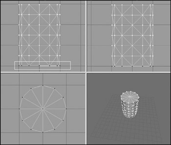
Figure 13.8: Selecting the bottom vertices. -
Choose Edit, Hide Selection. The dots of the vertices will disappear. This means that none of the vertices for the bottom face are selectable.
-
Now click Face. Make sure that By Vertex is selected.
-
In the Top view, select the vertex in the center of the can, as in Figure 13.9. Because you had hidden the bottom vertices, only the single center vertex for the top of the can has been selected. And because you are actually selecting faces by vertex, then all the top lid faces—and only those faces—have been selected.

Figure 13.9: Selecting the center vertex. -
In the Groups tab, click Regroup. This will create a new mesh with only the faces from the top of the can. The mesh will be named "Regroup01". Rename this mesh to "lid" in the same manner that you did earlier when you renamed the cylinder mesh to "can".
-
Switch back to the Model tab. Your lid mesh should still be selected.
-
Click the Move button, and then click and drag in the Side view to move the lid up and to one side from the rest of the can.
-
Click the Rotate button, and then click and drag in the side window to rotate the lid as if you were bending the lid back (see Figure 13.10).
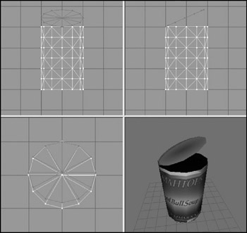
Figure 13.10: The can with lid opened. -
If necessary, repeat step 8 to position the lid properly. You might have to adjust it in one of the other views, depending on how you initially moved the lid.
-
Choose the Groups tab and click Regroup. The lid faces will now be part of their own group.
-
Choose Edit, Duplicate Selection. Another copy of the lid will be made in exactly the same location as the original.
-
Select Face, Reverse Vertex Order. This will invert the normals of the lid's faces, making it viewable from the other direction. You will recall that the normal of a face is, in the simplest terms, the direction that a face is facing.
-
On the Groups tab, add the original lid to your selection by clicking on the first lid group.
-
Select Vertex, Weld Together. Now the original lid is viewable from one side, and the copy is viewable from the other. They now share the exact same vertices.
If you rotate your can in the 3D view, you'll see that your lid now has the lid part of the skin on both sides. You'll also notice that the inside of the can is black. This is because no faces are normalized to the interior, just as the lid at first did not have any faces normalized on the side.
Tip You may be wondering why you didn't have to assign a material to the new faces you created with the Duplicate command. What happened is that when you grouped the original faces and the new faces together, the material that was assigned to the original lid faces were automatically assigned to the new group.
-
Repeat the above steps but this time create a set of faces for the can body that are normalized to the interior instead of the exterior, and then group them together. You can use your UV mapping and Paint Shop Pro skills to create a more realistic metallic interior to the can, instead of just repeating the exterior skin on the inside.
-
Save your work—you never know when a nice can of soup may be needed for dipping your towel in!
So, here we are. You've made a model of an object, using a couple of shape primitives. And you've learned how to make double-sided textures, rotate and move meshes (or groups), and assign skins. Feel free to explore your new capabilities. Poke around and try out the other primitives.
Menus
MilkShape can perform many more features and operations than what we've just gone over. In later chapters you'll learn how to make more difficult and challenging shapes, like player-characters, vehicles, and weapons. In this chapter we'll take a look at the program itself in more detail.
Most but not all of the menus have shortcuts assigned to the keys. Typically, the ones that are used the most do have shortcuts. If you want to add your own shortcut, you can use a plug-in to do that. We'll cover that when we discuss the Tools menu.
File
As in most Windows programs, operations in the File menu (see Figure 13.11) relate either to the creation and saving of files or to making global alterations to the current file's properties or contents. See Table 13.3 for more detail.
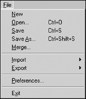
Figure 13.11: The File menu.
| Command | Description |
|---|---|
| New | Creates a new blank workspace. If the current workspace is not empty, then the user is prompted to save changes or continue without saving. Only one workspace can be open at a time. |
| Open | Opens an existing MS3D formatted file using the standard Open dialog box. |
| Save | Saves the current workspace as an MS3D file, providing that the current workspace has a name. If the workspace is unnamed, then the command will behave like Save As. |
| Save As | Requires the user to specify a new file name under which to save the workspace contents. |
| Merge | Merges together two MS3D documents: the current workspace and another workspace selected from file. |
| Import | Presents a submenu of file import plug-ins. This command works like the Open command, once an import plug-in is selected, except that some plug-ins offer import options in a user dialog box. |
| Export | Presents a submenu of file export plug-ins. This command works like the Open command, once an import plug-in is selected, except that some plug-ins offer additional export-specific options in a user dialog box. |
| Preferences | Presents the Preferences dialog box. This allows the user to set definable global application attributes and behaviors. |
| Exit | Exits the MilkShape program. The user is prompted to save changes if there are any that haven't been saved. |
Edit
The MilkShape Edit menu (see Figure 13.12) contains commands that assist the user when modifying models. It does not have Cut, Copy, or Paste but does offer commands in a similar vein for duplicating, hiding, and selecting objects. See Table 13.4 for more detail.
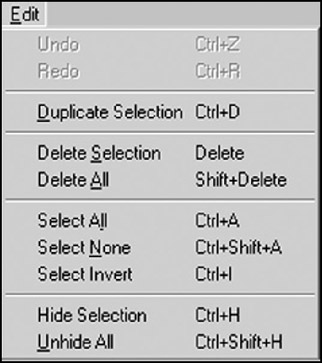
Figure 13.12: The Edit menu.
| Command | Description |
|---|---|
| Undo | The workspace is reverted back to the state it was in before the last user operation. |
| Redo | The workspace is reverted back to the state it was in before the Undo operation. |
| Duplicate Selection | All selected objects are duplicated in place. This command selects the new duplicates and deselects the previously selected objects. |
| Delete Selection | The currently selected objects are deleted. |
| Delete All | All objects in the workspace regardless of their selection state are deleted. |
| Select All | All objects in the workspace are selected. |
| Select None | All objects in the workspace are deselected. |
| Select Invert | All objects that were selected are deselected, and all unselected objects are selected. |
| Hide Selection | The selected object is hidden from view. This operation can also be performed on groups using the Groups tab in the toolbox. |
| Unhide All | All objects in the workspace are shown. |
Vertex
You can perform a number of operations on vertices in a model. They are available through the Vertex menu (see Figure 13.13). In most cases you will need to ensure that you've selected only vertices in a model or at least have the selection mode set to Vertex. See Table 13.5 for more detail.
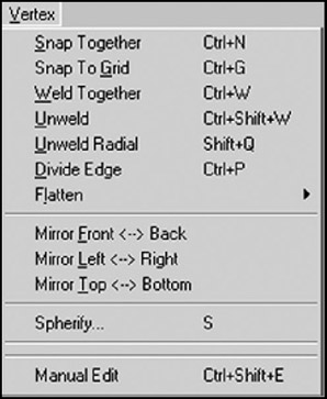
Figure 13.13: The Vertex menu.
| Command | Description |
|---|---|
| Snap Together | Snaps all the selected vertices together. The middle point between all selected vertices becomes the new location for the vertices. |
| Snap To Grid | Moves all selected vertices to be in line with the smallest grid X, Y, and Z position (to see the smallest grid positions, zoom all the way in). The grid size can be changed using the File, Preferences menu. |
| Weld Together | Creates one vertex at a precise point where several vertices exist. Only selected vertices are welded together. This is the way you would join a seam of two or more abutting faces. |
| Unweld | Splits each selected vertex into multiple vertices. The number of vertices created depends on the number of faces the original individual vertices were bound to. For example, a vertex with three faces attached will be split into three vertices. |
| Unweld Radial | Is the same as Unweld but will also shift the unwelded vertices away from each other in a circular pattern. The vertices will move from the origin at which they were unwelded by half the distance from the origin to the nearest edge. |
| Divide Edge | Divides a face between two selected vertices into two faces. The procedure will only work with two vertices selected. This has no effect on vertices without any faces in common. |
| Flatten | Presents a submenu for the user to align all selected vertices to the same point on the X, Y, or Z plane. This is similar to Snap Together but it works on only one axis instead of all three. |
| Mirror Front <–> Back | Mirrors, or flips, the currently selected object along the Z-axis. |
| Mirror Left <–> Right | Mirrors, or flips, the currently selected object along the X-axis. |
| Mirror Top <–> Bottom | Mirrors, or flips, the currently selected object along the Y-axis. |
| Spherify | Calculates a bounding sphere and attempts to place the selected vertices on the surface of the sphere. It can be constrained in all three dimensions, and the bounds can be manually set. |
| Manual Edit | Allows the exact placement of one selected vertex with floating point accuracy in the X, Y, and Z planes. |
Face
The Face menu (see Figure 13.14) provides commands for manipulating triangles and faces in the workspace. See Table 13.6 for more detail.
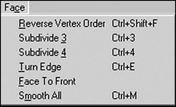
Figure 13.14: The Face menu.
| Command | Description |
|---|---|
| Reverse Vertex Order | Changes the order of the vertex winding, which changes (negates) the normal of the face. This will turn a face inside or outside depending on its current vertex order. Counterclockwise vertex winding creates an outward face on an object. |
| Subdivide 3 | Divides each selected face by three, creating three faces out of one. |
| Subdivide 4 | Divides each selected face by four, creating four faces out of one. |
| Turn Edge | Is performed on two triangles with a common edge. The common edge is removed, and a new edge is created between the two vertices (one from each triangle) that weren't previously joined by an edge. |
| Face To Front | Is used on selected faces to change all vertex orders to counterclockwise, outward-facing vertex ordering, or winding. |
| Smooth All | Is used to smooth all faces after construction of parts of a model. |
Animate
The Animate menu (see Figure 13.15) is used to manipulate animation frames in the model via the Keyframer. See Table 13.7 for more detail.
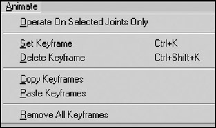
Figure 13.15: The Animate menu.
| Command | Description |
|---|---|
| Operate On Selected Joints Only | When this menu item is toggled on (checked), then only the joints that are currently selected will have their pose data stored for the current keyframe. |
| Set Keyframe | This stores the pose of the skeleton to the current keyframe (whichever keyframe that's in the keyframe number box). |
| Delete Keyframe | This removes the stored skeleton pose from the current keyframe. |
| Copy Keyframes | This copies the skeleton pose from the current keyframe. In order for the copy action to perform correctly, the user must first select the skeleton in the keyframe to be copied from. |
| Paste Keyframes | This pastes the copied skeleton pose to the current keyframe. After the keyframe has been pasted, you need to immediately set the keyframe in order to preserve the skeleton pose. |
| Remove All Keyframes | This removes all stored skeleton poses at all keyframes in the animation timeline. This is effectively the same as deleting the animation. |
Tools
The Tools menu (see Figure 13.16) provides access to both built-in tools and user plug-in tools. The functions available are not the same as those available in the toolbox. This is a potential source of confusion. See Table 13.8 for more detail about the Tools menu.
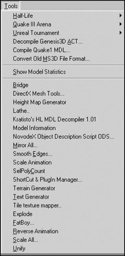
Figure 13.16: The Tools menu.
| Command | Description |
|---|---|
| Half-Life | This command contains several options used to create and save Half-Life models. |
| Quake III Arena | This command saves a Quake III control file to the directory you specify in the save window. |
| Unreal Tournament | This command contains options for creating male and female skeletons using the default Unreal Tournament skeleton configurations. |
| Decompile Genesis-3D ACT | This command allows you to decompile an ACT model used by the Genesis 3D engine. |
| Compile Quake1 MDL | This option will compile a Quake1 MDL file, used in the Quake 1 engine. |
| Convert Old MS3D File Format | This command converts a file from an old version of the MilkShape 3D file File format. The command can be used to change files created with MilkShape 3D versions 1.4.0 and earlier. |
| Show Model Statistics | Brings up a statistics window showing useful statistics, such as the number of faces and vertices in the workspace. |
| Plug-Ins | The list of plug-ins available is user-configurable using the Shortcut and Plug-In Manager. Not all plug-ins are distributed with MilkShape. See the MilkShape sidebar for descriptions of currently available plug-ins. To get the most up-to-date information about plug-ins, visit chUmbaLum sOft's Web site: http://www.swissquake.ch/chumbalum-soft. |
There is quite a large list of MilkShape plug-ins that extend MilkShape's capabilities. For information about where to find them to download, tutorials about how to use them, and the names of the individual creators, see Appendix B, "Game Development Resources on the Internet." The plug-ins that were known at the time of this writing are listed; some plug-ins are import or export filters for different file formats and aren't included here, except for the Torque DTS Exporter, because we use it in this book (the Wavefront OBJ Importer and Exporter are built into MilkShape).
-
ms2DTSExporter. This plug-in exports models, animations, and materials to DTS model format for use with the Torque Engine. This plug-in appears in the File, Export menu.
-
msSelectionEditor. This plug-in edits the selection from a 3D view. There are a lot of options and you can read some detailed information about it here.
-
msTimer. This plug-in lets you time how long you've been working on a certain model.
-
msEdgeExtrude. This plug-in lets you extrude edges in addition to faces.
-
msJointTool. This plug-in allows you to add joints in the middle of the hierarchy, unlink a joint from a hierarchy, and assign vertices to the closest joint (some kind of "Assign Mesh to Skeleton" tool).
-
msSnap. This plug-in snaps not only to 1.0, it also snaps joints.
-
msToolArray. This plug-in duplicates objects and then places the duplicates in 3D space according to user specifications.
-
msVertexPlane. This plug-in is similar to the Vertex, Flatten command, except that it snaps selected vertices to a plane instead of a single point.
-
msToolFatBoy. This plug-in will make your model fatter or thinner. This is useful for tweaking player and monster characters.
-
msOperationMirrorAll. This plug-in will mirror everything about your model over the selected plane: bones, mesh, animation—everything.
-
msToolReverseAnimation. This plug-in will reverse the order of the keyframes in whatever animation you have loaded.
-
msToolScaleAll. This plug-in applies scale to all objects in the workspace at once.
-
msSelPolyCount. This plug-in shows the selected polygon, vertex, and unique vertex counts, as well as how many polygons there are per group.
-
msBridge. This plug-in creates a mesh connecting to previously independent meshes or groups.
-
msTerGen. This plug-in can generate random terrains or import a bitmap file to use as a height map.
-
msTextGen. This plug-in generates 3D objects in the form of text.
-
msModelInfo. This plug-in provides more detailed information about a model than the Show Model Statistics command.
-
msTileTextureMapper. This plug-in generates texture coordinates to geometry for tile textures (also known as seamless textures).
-
msLathe. This plug-in takes flat geometry and turns it around the X-axis to build a 3D model.
You can install plug-ins by simply copying them to the MilkShape directory and then launching MilkShape. They will then appear under the Tools menu beneath Show Model Statistics.
Window
The Window menu (see Figure 13.17) provides commands that determine what information is available in the MilkShape window and how it is displayed. See Table 13.9 for more detail.
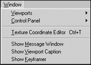
Figure 13.17: The Window menu.
| Command | Description |
|---|---|
| Viewports | This command presents a submenu that allows you to pick an alternative viewport layout. The four-pane layout with three 2D views and one Perspective view is the default. |
| Control Panel | This command allows the user to set whether the toolbox frames appear on the left or right of the main window. The right side is the default. |
| Texture Coordinate Editor | This is for adjusting where textures appear on the model. Although useful, it is not as powerful or flexible as using a dedicated UV Unwrapping or Mapping tool like UVMapper. |
| Show Message Window | This option shows a script output window that holds the results of compiling various types of models for specific games. |
| Show Viewport Caption | This command shows details about the viewport it appears above. From left to right, the details are the view, the field of view, the near clipping plane, and the far clipping plane. |
| Show Keyframer | The Keyframer is the animation box along the bottom of the main window. It is used to create keyframe positions of bones and joints in a skeleton for animation. |
The Toolbox
Way back near the start of this chapter, in Figure 13.2, is a depiction of the contents of the various tabs in the toolbox. In this section here we will dig deeper into the capabilities in those tabs. Table 13.10 provides a brief summary of each toolbox tab's functions.
| Tab | Purpose |
|---|---|
| Model | This is used for the placement of vertices and shape primitives, as well as for the construction of polygons and skeletons. |
| Groups | This contains commands used to group vertices and polygons. Groups can also be created from existing polygons. |
| Materials | This deals with the creation of materials, including textures from file, ready to be assigned to groups. |
| Joints | This contains tools for manipulating and managing skeleton joints. |
You should understand that, in general, when using the functions in the toolbox, we will first have to select some object via one of the views and then operate on it using one of the toolbox commands. This sort of noun-verb operation mode requires us to make sure we have the appropriate objects selected before every action we take.
The Model Tab
The Model tab (see Figure 13.18) contains the tools necessary to create and modify the basic shape primitives: vertices, faces, cylinders, spheres, and cubes (boxes, as MilkShape calls them). Table 13.11 shows the functions of the Model tab's buttons.
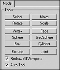
Figure 13.18: The Model tab.
| Button | Description |
|---|---|
| Select | This tool puts the program into select mode so that the user can select any object or collection of objects on one of the wire-frame views. Once you are in select mode, you can specify one of four different selection target types: vertex, face, group, or joint. You also have two optional settings: ignore backfaces and by vertex (which is only available in face selection mode). |
| Move | This tool permits you to move any selected objects by clicking in the appropriate wire-frame view and dragging the cursor. You can also specify discrete movement by entering numbers in the Move Options boxes at the bottom. |
| Rotate | This tool permits you to move and rotate any selected objects around a single axis by clicking in the appropriate wire-frame view and dragging the cursor up or down. You can also specify discrete rotations and multiple axes rotations by entering numbers in the Rotate Options boxes at the bottom. |
| Scale | With this tool you can change the size of any selected objects along one of two available axes in each view by clicking in the appropriate wire-frame view and dragging the cursor up, down, left, or right. You can also specify discrete scaling and multiple axes scaling by entering numbers in the Scale Options boxes at the bottom. |
| Vertex | Use this tool to place individual vertices, one at a time, in a wire-frame view. In each different view, the vertex will be placed at the zero axis position for whichever axis is not presented in the view. This tool has no options. |
| Face | With this tool you can connect individual vertices to create a face, one vertex at a time, with three vertices defining a face. The Threshold option specifies how close to a vertex you need to click to add it to the current face you are building. As you build the face, select the vertices in a counterclockwise direction to create an outward normalized face. |
| Sphere | This tool is a shape primitive tool. To create a sphere, simply click and drag the cursor in a wire-frame view. With the Sphere options you can specify the number of slices (like the slices in a pie) or stacks (like a stack of pancakes) that make up your sphere. |
| GeoSphere | Use this tool to create more realistic spheres using a different program technique. You use the tool the same way as the Sphere tool, but you can only specify the complexity of the sphere using the Depth option. |
| Box | Use this tool to create cubes. Just click in a wire-frame view and drag until it has reached the size you want. |
| Cylinder | Use this tool the same way as you use the Sphere tool, even including the specification of stacks and slices. |
| Extrude | This tool operates only on the faces. If you have two faces aligned to create a flat surface, like a piece of cardboard, you would use this tool to extend the surface in a specific direction to create a box. Just click the mouse and drag to perform the extrusion. Using the Extrude options you can specify which directions to do the extruding in—normally you would use only one direction at a time. The Smoothing option tells the program to smooth shade the polygons as it draws the extruded shape. |
| Joint | This tool places special joint objects. It works the same as the Vertex tool, except that if an existing joint is already selected when you make the new joint, the new joint will be attached to the previous one by a bone. If the Show Skeleton option is turned on in the Joint tab, the bone will be visible in yellow. |
| Redraw All Viewports | If you have this option turned on, then every time you perform one of the tool operations, the views in all the viewports will be redrawn to reflect your changes. |
| Auto Tool | If you have this option turned on, then the program will alternate between any tool and the Select tool each time you finish an operation. This option is handy for tweaking and repetitive adjustment techniques. |
The Groups Tab
You will often want, or need, to organize your model faces into groupings that make either visual or logical sense. Whether you organize them as meshes that make visual sense or simply as logical groups, you do this with the Groups tab, shown in Figure 13.19. The Torque DTS Exporter uses special groups with the name collision to define collision meshes. Table 13.12 presents the functions available from the Groups tab.
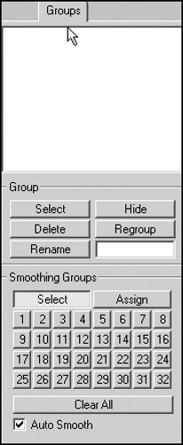
Figure 13.19: The Groups tab.
| Button | Description |
|---|---|
| Group Selector Box | This is the white area at the top. It contains the names of the groups, one group per line. You always need to choose a group from this box before performing any group operations. |
| Select | When you use this tool, the currently chosen group in the list will become selected in the wire-frame views—that is, it will become drawn in red. Each time you choose a different group and click the Select tool, that group gets added to each view's selection. |
| Hide | With this tool you can make the chosen group's faces and vertices become invisible. This is useful for uncluttering a view or to ensure that you don't select the wrong parts for another operation. |
| Delete | Use this tool to permanently remove a group from the model. |
| Regroup | With this tool you create new groupings from whatever model elements are selected (shown in red) in the views. Any elements that already belong to other groups are removed from those groups and added to the new group. |
| Rename | Choose a group, type a new name in the Rename box, and then click the Rename tool. Bingo! The group now has a new name. |
| Smoothing Groups Select | Pressing this key and then one of the Smoothing Group numbers selects the polygons assigned to that Smoothing Group. Smoothing Groups can only be selected on the numbers that have been assigned. |
| Smoothing Groups Assign | When you have a group of polygons selected you can press this button and then one of the Smoothing Group numbers to assign all selected polygons to a Smoothing Group. Additional groups of polygons can be added to the same group without overwriting the previous contents of the Smoothing Group. |
| Smoothing Group Numbers | These numbers act as a storage bank for groups of polygons. They can have polygons assigned to them and selected from. If the Auto Smooth check box is selected, assigning groups of polygons to a Smoothing Group number will smooth shade them (Smooth Shaded shading has to be enabled to view the effect of this—right-click the 3D Perspective view and click Smooth Shaded from the pop-up menu). |
| Smoothing Group Clear All | This button removes the assigned Smoothing Groups from the Smoothing Group numbers. The polygons will remain smooth shaded, but they will no longer be in the same Smoothing Group. |
| Smoothing Group Auto Smooth wish | When assigning Smoothing Groups, ensure this is checked if you the selected polygons to be smooth shaded. |
The Materials Tab
With the Materials tab (see Figure 13.20), you can define the textures that will be used to skin your model, as well as what characteristics they will have when displayed. Special materials are also used to define certain model characteristics to the Torque DTS Exporter. Table 13.13 explains the functions of the Materials tab.
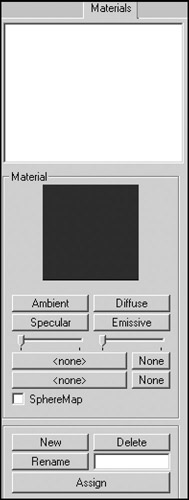
Figure 13.20: The Materials tab.
| Item | Description |
|---|---|
| Material Selector Box | This is the white area at the top. It contains the names of the materials, one material per line. You always need to choose a material from this box before performing any material operations. |
| Material Preview | The currently chosen material is displayed, mapped onto a sphere. You can click and drag the sphere with the mouse to view hidden parts of the material map. |
| Ambient | Use this tool to get a color picker window for setting the ambient light of the environment the material is in. This attribute affects the color and the intensity of the color that the material reflects. |
| Diffuse | Use this tool to get a color picker window for setting the light that the material will directly reflect. This attribute has the most influence over the color of the material. |
| Specular & Specular Slider | Use this tool to set the specular highlight of the material. Basically, selecting a bright color will create a highlight on the material of the color chosen. Moving the slider below it changes the focus of the highlight. The highlight can range from appearing as a small spot to appearing as if the object is immersed in incandescent light. |
| Emissive | Use this tool to get a color picker window for setting the color and intensity of the light that the material emits. This attribute will appear as a glow around the material. |
| Transparency Slider | This slider adjusts the amount of transparency that an alphamap applies to a texture and the faces that the texture is assigned to. You must click Assign or click in the viewport to update the model to reflect your changes. |
| Texture Browse Button | Use this tool to select a texture to apply to the material. Pressing it will reveal a Windows Explorer browse box from which image files can be selected. The None button beside this button removes the texture file from the material. |
| Alphamap Browse Button | Use this tool to apply an alphamap to the material. A black-and-white image can be used to remove areas of texture where there may be holes. Black is fully occluded and white is fully visible; it is possible to use variations of gray to achieve semitransparency. The None button beside this button removes the alphamap file from the material. |
| New | The New button, when pressed, will create a new blank material with default attributes, no texture or alphamap files, and a default name. |
| Delete | To delete a material, choose it in the Material Selector, and then click the Delete button. This literally removes the material from the workspace, so use this wisely. |
| Rename Button & Box | To rename a material, choose it in the Material Selector box, type the desired name in the box next to the Rename button, and then click the Rename button. |
| Assign | Use this tool to assign the chosen material in the Material Selector box to the selected group. |
The Joints Tab
Using the Joints tab (see Figure 13.21), you can specify the joints for skeletons, which are used in animations. Joints are also used as substitutes for the concepts of special nodes that are used by the Torque DTS Exporter. Table 13.14 describes the Joints tab functions.
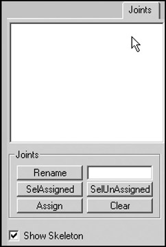
Figure 13.21: The Joints tab.
| Item | Description |
|---|---|
| Joint Selector Box | This is the white area at the top. It contains the names of the joints, one joint per line. You always need to choose a joint from this box before performing any operations on joints. |
| Rename Button & Box | These tools work the same as the Rename tools in the other tabs: Choose a joint, type a new name in the box, and then click the Rename button. |
| SelAssigned | After you have chosen a joint, press this button to select all the vertices assigned to that particular joint. |
| SelUnAssigned | Press this button to select all vertices not assigned to the chosen joint. |
| Assign | Use this tool to assign vertices to a joint. To do this, choose the Select-Vertices tool from the Model tab, highlight the joint in the Joint Selector box that you wish to assign the vertices to, and then select the vertices and click Assign. |
| Clear | Press this button to clear all the assigned vertices from belonging to the chosen joint in the Joint Selector box. |
The Keyframer
The Keyframer (see Figure 13.22) is a special tool used for defining animations for your model. With it, you can save skeletal positions in a model. You then produce animation by storing several keyframes to the Keyframer and playing them back. There is a set of controls for managing the playback. Typically, only frames where changes take place need to be set by the user; hence the term keyframe—they are key to the animation. MilkShape 3D will fill in the pose or position frames between the keyframes. You must click the Anim button at the lower right in order to work with the Keyframer.
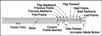
Figure 13.22: The Keyframer.
Table 13.15 describes the primary Keyframer functions.
| Component | Description |
|---|---|
| Keyframe Slider | Use the slider to preview your animation before playing it. Using the slider, you can move freely backward and forward between the frames with mouse movement instead of pressing the Play Forward and Play Backward buttons to see the animation. It is useful for selecting animation frames in smaller animations; use the Frame Position box to select frames for larger animations with many (more than a dozen or so) frames. |
| Playback Controls | The playback controls allow you to view your animation in MilkShape 3D in a manner similar to a VCR or DVD player. From the left, the buttons are First Frame, Previous Keyframe, Previous Frame, Play Backward, Play Forward, Next Frame, Next Keyframe, and Last Frame. All of these commands update the model to the current frame, and the slider is also moved to the appropriate frame. |
| Current Frame Number Box | Use this box when you have a lot of frames in your animation and the slider does not allow the accuracy you desire when selecting frames. You can type in a value here that will set the number of frames in the animation. The box will accept a whole number to indicate the frame to which you wish to go; the slider and view will change to reflect the selected frame. |
| Total Frames Box | In this box, enter the number of frames you want in your animation. Most modelers choose a relatively high number, depending on the number of animations the model is to perform, and key in animations between certain numbers of frames leaving a three- or four-frame gap between animations. With a Run, Walk, Jump, and Shoot animation, you would key in the Run animation first and then leave several frames, key in the Walk animation and then leave several frames, and so on. |
| Animate Button | This button enables the Keyframer. It behaves like a toggle—when down, the Keyframer is enabled; when up, the Keyframer is disabled. |
The Preferences Dialog Box
The Preferences dialog box (see Figure 13.23), which you reach by choosing File, Preferences, has two tabs. The Viewport tab is used to set up the viewports' attributes, and the Misc tab offers miscellaneous settings. Table 13.16 provides details about each setting in the two tabs.
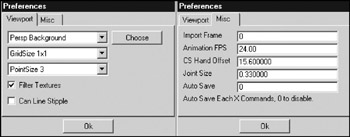
Figure 13.23: The Preferences dialog box.
| Component | Description |
|---|---|
| Property Selector | With MilkShape, the user can customize the colors of components used when modeling. The drop-down list contains the component names; a color for the selected component can then be chosen by clicking the Choose button next to the drop-down box. Following is the complete list of color customizable components: |
| Grid Size | Use this control to set the spacing of the grid lines in the wire-frame views. The default grid size is 1 1; this gives the smallest line spacing. The grid size you use usually depends on the scale of the models you are building. |
| Point Size | Use this control to specify the size of the vertex points displayed in the wire-frame views. Larger point sizes are easier to see and to select individually, but they may tend to obscure model details in crowded areas at low view magnifications. |
| Filter Textures | When set, this turns on mipmapping texture filters. This will smooth the texture so that the rasterized pixels are not as noticeable. |
| Can Line Stipple | When moving, scaling, or extruding objects, MilkShape draws a guideline that indicates the vector of the action, denoting its direction and magnitude. This is usually a solid line, but with this option set, it is rendered as a dashed or dotted line. This also stipples the box line used for multiple selections. |
| Import Frame | This allows the user to specify the animation frame to be imported from MD2 or MD3 files using the Morph Target Animation mechanism. |
| Animation FPS | This specifies the playback speed of animations in Frames Per Second (FPS). |
| CS Hand Offset | This is used to specify the offset for either side of a decompiled CounterStrike model. |
| Joint Size | This allows the user to set the display size of the joints that are used in MilkShape. You should change the size to reflect the scale of the model you work with. |
| Auto Save | This option allows you to specify how often the program will automatically save your work. The frequency is defined by how many commands or operations you want to be able to perform before the save happens. This option can be a lifesaver but can also be a nuisance if you set the value too low—especially if you are doing a lot of experimenting and undo your previous operations frequently. A setting of about 10 seems to work well. |
Other Features
MilkShape has a few other features that we won't cover in great depth, but two that deserve at least an honorable mention are the Texture Coordinate Editor and the Message Panel.
The Texture Coordinate Editor provides primitive texture-mapping capability. It has some rather severe limitations that prevent it from being used in even moderately complex models. The biggest limitation is that it doesn't unwrap meshes independently. For this reason we use external tools, like UVMapper. UVMapper may be a bit more awkward to use, because it isn't integrated, but it does a better job, providing more flexibility and control.
The Message Panel displays output from executing plug-ins and modeling operations. It can be useful for providing insight into how MilkShape does its work, but its downfall is the screen space it takes up.
EAN: 2147483647
Pages: 197