Section 18.3. ASPECTS AT DESIGN LEVEL
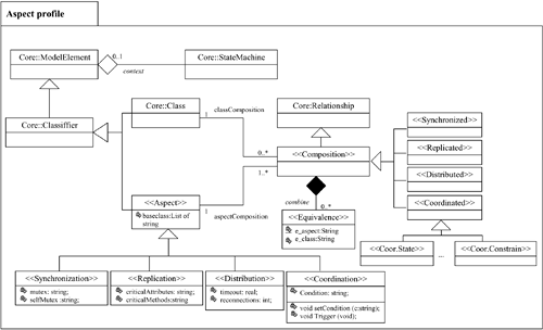
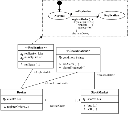
18.3. ASPECTS AT DESIGN LEVELThe aim of this section is to demonstrate how the problems stated previously can be overcome by obtaining a correspondence between implementation and design. To achieve this, two different approaches have been followed in our group. The first is extending UML with an aspect profile. In this profile, each aspect is represented with a new stereotype. With this, a notation to describe the behavior of a system based on aspects is provided. However, with UML, there is no way to make formal specifications. This is a requirement for different parts of several systems. In these cases, we introduce aspects at the architectural level. In Section 18.3.1, using the broker example, we present a rough description of the UML extension. In Section 18.3.2, we outline the work on software architectures and aspects. 18.3.1. Aspects in UMLAlthough UML does not directly provide elements to define aspects, its semantics can be extended by introducing new stereotypes, constraints, and tagged values. In the last several years, different approaches to introducing the notion of aspects in UML have been followed. The most recent can be seen in [2]. In [14], a new stereotype is provided to specify aspects, but in a generic way. This stereotype does not provide elements to specify the meaning of individual and real aspects. In [8], three new stereotypes are considered to describe specific aspects: synchronization, distribution, and replication. In [6], aspects are represented as packages that contain standard design models to represent the structure and behavior of the aspect. Extensions to the UML's notion of templates are used to represent those points in a base design where the aspect should be weaved. A new kind of relationship, the composition relationship, is used to specify how the aspect should be composed with a base design model. However, in all these cases (and others such as those proposed in [5, 10]), there is a direct extension of the UML metamodel. There appears to have been no explicit effort in any of these approaches to ensure that the extensions (e.g., new stereotypes or metamodel elements) are localized or grouped within the metamodel. This makes understanding the new language constructs at the metamodel level more difficult. An alternative to this view is describing aspects with stereotypes but grouping them in a profile. In [1], the specification of a UML aspect profile is proposed. This work defines the aspect concept in a general way, without specifying the meaning of the new metamodel entities when designing different kinds of aspects. This is the approach we follow in our project, but we include new elements in order to specify different kinds of aspects. A profile is a predefined set of stereotypes, constraints, and tagged values that specializes UML in a specific domain. A profile does not include additional basic elements. Conversely, it offers mechanisms that help in the application of UML to different domains. In our case, a new UML profile has been created for the application of UML to the generic domain of aspects. To be more precise, four aspects are considered: synchronization, distribution, replication, and coordination. This new profile has been called Aspect Profile (see Figure 18-4). The first element defined in this profile is a stereotype called <<Aspect>>. It contains a reference to the class or classes with which it is associated. This stereotype is based on the classifier element from the core package. Deriving from it, there are stereotypes for the aspects of synchronization, replication, distribution, and coordination. Each aspect has its own attributes. Every aspect is associated with one or more classifiers. A class can be related to zero or more aspects. The type of association between a class and an aspect specifies the composition between both elements. The composition stereotypes are based on the relationship element from the core package. Because coordination is a more complicated aspect, there are different composition stereotypes for this aspect. These stereotypes are based on the event notifications needed for coordination [11]. Figure 18-4. Aspect profile. When representing a particular aspect, different issues have to be taken into accounton one hand, the static structure and dynamic behavior of the aspect, and on the other hand, the association between classes and their aspects. Next we show how UML has been extended to consider these three issues. Figure 18-5 supports the explanation and illustrates an aspect-oriented solution to the broker example using the proposed UML extension.
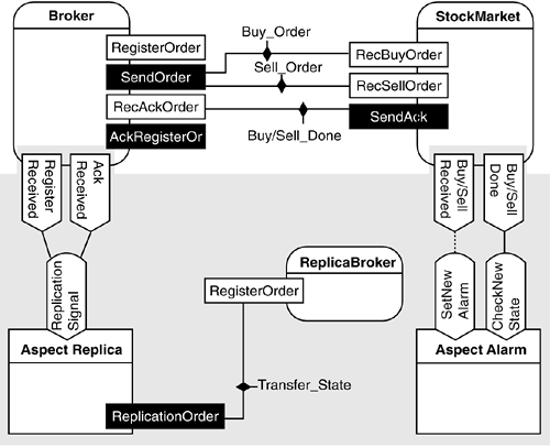
Figure 18-5. The example with the UML extension. 18.3.2. Aspects from the Software Architecture PerspectiveAnother alternative to dealing with aspect-oriented design is concerned with description issues at the level of the software architecture. Although this work is still at an early stage, the first results are being obtained. Currently, software architects do not have tools to adequately deal with the separation of crosscutting concerns when specifying the architecture of software systems. Current architectural description languages (ADLs) do not provide primitives to specify aspects. Using ADLs, software architects are able to specify the functionality of the system by means of components and the interaction between components by means of connectors. For example, to specify the structure of the broker example from Section 18.2.1, the software architect would introduce two components (Broker and StockMarket) with their ports and would specify the interaction among them using connectors. However, some concerns (like Replica and Alarm) cut across the structure of the system. Such concerns must be understood as property specifications crosscutting the description of components and connectors.[3] In order to separately specify such concerns, new elements are required in the ADL. Figure 18-6 shows the specification of the broker example using AO-ADL.[4] The top of the figure (white area) shows how the software architect has specified the Broker and the StockMarket components and the interaction between them through ports. White ports represent "in" ports, while black ports represent "out" ports. Each connector (Buy_Order, Sell_Order, and Buy/Sell_Done) specifies a complex interaction.
Figure 18-6. The example using AO-ADL. The bottom of Figure 18-6 (grey area) shows some of the elements that our approach introduces to manage the separated specification of crosscutting concerns at the software architecture level. In particular, the figure shows the alternative followed to separate the Replica and Alarm aspects (from Figure 18-3) using AO-ADL. The capabilities supported by AO-ADL can be summarized as follows:
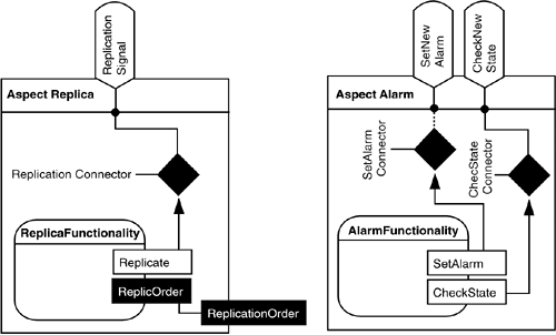
For example, in Figure 18-7, the specification of the Replication connector states that each time that the ReplicationSignal role is applicable (in fact, every time the Broker arrives to the RegisterReceived or the AckReceived join points), the Replicate functionality executes. The SetAlarm connector states that when the SetNewAlarm role is applicable, the SetAlarm functionality executes. Additionally, this connector checks the current state of the market and blocks the execution of the service that made the role applicable (Sell or Buy) until the market satisfies the conditions to buy or sell. As the reader can see, connectors can be complex entities. Continuing this process, the software architect deals with the detailed design of the system. When it is done, he will be able to give precise guidelines to the programmer about how to manage the separation of crosscutting concerns in the system. In this way, the problems stated in Section 18.2.2 are avoided. |
EAN: 2147483647
Pages: 307
