Discussion
The models you choose to make shape the worldview you have of the problem space and the solution. Models, like technology, are never neutral. The best models simplify a reality, but the reality they model is itself constructed and part of a worldview (situated simplicity).
5.1 STANDARD DIAGRAMS
| PROBLEM | How to organize the presentation of model information to minimize overhead and maximize transparency. |
| CONTEXT | Building models with the UML. |
| FORCES |
|
| SOLUTION | Combine the graphical elements available in the UML into a limited and repeatable set of semantically meaningful diagram types. These types should represent categories of information that are useful to the viewer. In general, rather than inventing your own diagram types, stick with the standard diagram types that are explicitly supported by the UML (as described in Chapter 3, "UML Essentials, Elements, and Artifacts" ). |
| RESULTING CONTEXT | Shareable diagrams that rely on conventions to provide a significant amount of meaning. |
| DISCUSSION | In the UML, any combination of presentation elements is permitted there are no limits to which graphical components of the UML may be combined in a diagram, and diagram meaning is mainly provided by semantics. |
| Diagrams organize information within a semantic domain and within a model, and so they must be internally consistent (with all elements representing the same type of information) and consistent with the scope of the semantic domain. |
5.2 IMPLEMENTATION OR REPRESENTATION
| PROBLEM | Modelingin a purposeful and focused way. |
| CONTEXT | The modeling activity in general, but especially the early stages of a project, during conceptualization and analysis. |
| FORCES |
|
| SOLUTION | Distinguish between implementation models and representation models when doing modeling. In particular, distinguish between models that are meant to document your understanding of the domain (representation models) and those that are closer to blueprints plans for the solution (implementation models). For each model that you build, determine who the audience is and what purpose it will serve. |
| Although it is no longer expected that the problem space and the solution space will be kept hermetically separated during development (and addressed sequentially), it is still important to avoid adding implementation details in too early or inappropriately. It is also important to stay aware that programming languages usually don't have the flexibility or the constructs needed to translate a model directly into code. | |
| RESULTING CONTEXT | Focused models that reflect their audience and intended use. |
| DISCUSSION | As object-oriented approaches have matured, they have been increasingly applied to areas of systems development other than design and construction. In particular, they are being used for analysis and specification, modeling domains and business areas, organizing requirements, and describing business processes. Although many object concepts overlap between the needs of representation and implementation, some (such as modularity) may not (Parsons and Wand, 1997). |
5.3 DIGESTIBLE CHUNKS
| PROBLEM | How to make models that work. |
| CONTEXT | Building models that reflect the way people's brains and perceptive faculties work. |
| FORCES |
|
| SOLUTION | Leverage the cognitive limitations of human perception and memory in building models. Instead of building models that include everything but the kitchen sink (and maybe even that), chunk your models into diagrams. They should be digestible bits that are individually meaningful and connected in a sensible fashion. A related pattern that is useful in figuring out how to build these digestible bits is, of course, Seven Plus or Minus Two. |
| RESULTING CONTEXT | Individual models that are easier to understand and manage mentally. |
| DISCUSSION | A variety of research over the last 20 years or so has indicated that there are definite cognitive patterns that constrain what we can understand and assimilate. These patterns seem to be there because we humans are natural pattern-building creatures, and without the limits suggested by cognitive patterns, we would be hamstrung by excessive and faulty pattern-recognition. So, rather than limits to human capability, cognitive patterns are a means to leverage the human predilection and capability for pattern making. |
5.4 ATTACH THE ACTOR
| PROBLEM | Clearly identifying the end-user roles to which a class or component in a system is responsible for providing services. |
| CONTEXT | Any portion of use-case driven model, especially implementation models (in which use case traceability is particularly lacking). |
| FORCES |
|
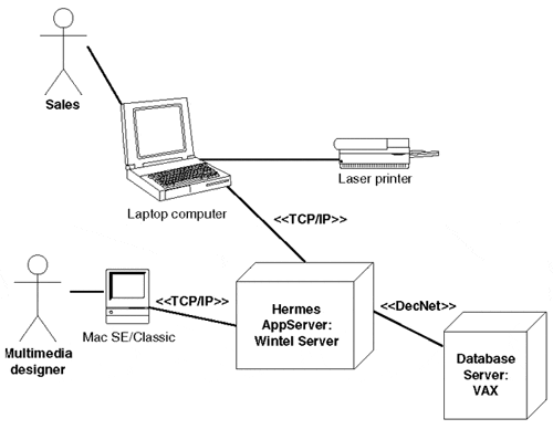
| SOLUTION | Given a system element (a class, object, component, state machine, interaction, node, and so on) in a UML model, attach the actor(s) for which it will be used to satisfy the use cases the actor is involved in. Figure 5.1 is the example of a simple graphic deployment diagram from Chapter 4,"Patterns of Style," augmented with appropriate actors. (They could be graphical icons instead of stick figures!) |
| DISCUSSION | By systematically attaching the actor to the system elements that are responsible for realizing the use case, the model will be able to directly identify the end-users to which they are accountable. |
Figure 5.1. Actors in deployment.
5.5 BUSINESS RULES INVARIABLY CONSTRAIN
| PROBLEM | Where can a UML model hold the business rules that guide system operation? Specifically, how can rules that describe fundamental knowledge in the domain be explicitly documented? |
| CONTEXT | UML analysis and design models in which the modeler has significant information about the domain itself that cannot be modeled using standard UML model elements. |
| FORCES |
|
| SOLUTION | Use UML constraints to describe conditions and limits between model elements that represent aspects of your application domain. For each business rule discovered during analysis and design, a declarative constraint should be attached to the model elements involved in the rule. The constraint must describe the rule in terms of a statement that is always true. |
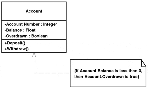
| Figure 5.2 shows a typical example of how a constraint can be used to capture a business rule. The diagram shown contains a single class, Account, which represents a bank account in the problem domain. Business rules are captured during the course of the development process, perhaps as a result of the alternate flow of a use case or specification document. In this example, it says that the Overdrawn attribute in the Account class must be set to true if the balance in the account falls below zero. | |
| The constraint that describes this business rule is shown as a UML note (rectangle with bent corner) that is attached through a dotted line to the Account class. When the system is implemented, the constraint can be realized as an invariant or other enforcement mechanism. The UML specification recommends (but does not require) that the constraint be defined in terms of the Object Constraint Language. The constraint can alternatively be defined in terms of the underlying implementation language, although is discouraged for reasons of clarity and portability. | |
| RESULTING CONTEXT | UML analysis and design models where business rules are modeled in a consistent and accessible manner. |
| DISCUSSION | Constraints are relationships between modeling elements that must always be true for the duration of system operation. Because constraints describe true/false relationships, they allow a means for specifying and controlling, in a deterministic fashion, the runtime semantics of systems. Because UML constraints map right into implementation artifacts, typically programming code, they can be used to verify whether the system complies with the business rules defined during the design phase. |
Figure 5.2. Attaching business rules.
5.6 DYNAMIC OBJECT TYPES
| PROBLEM | An object must change types by representing different but similar things at different times. |
| CONTEXT | Modeling any object whose role in a system changes over time. |
| FORCES |
|
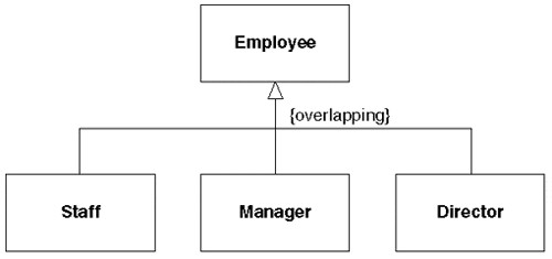
| SOLUTION | Enumerate the different types that the object can assume by using the generalization relationship, and then specify the overlapping constraint provided by the UML to describe that the object's type can vary during system operation. See Figure 5.3, in which an "overlapping" constraint implies that an object can change its type during its lifetime. |
| RESULTING CONTEXT | A description of the object that accurately reflects the different types the object can assume. |
| DISCUSSION | Both Fowler and Odell have made much of the dynamic classification issue, which surfaces time and again in conceptual models, but has poor support in most object-oriented programming languages (OOPLs). This disconnect has ramifications for many modelers because OOPLs have a tendency to impose their semantic limitations on the resulting implementation models. |
| Practically speaking, most programming languages can't support anything other than static classification: an object and its type have a one-to-one mapping. However, in reality the semantics of the domain may require that an object (such as a person object) have multiple types over time (for example, student, resident, and doctor). Therefore, semantically, although the entity stays the same over time but may have different behaviors and even different interfaces, the UML provides a mechanism for describing such behavior using a predefined constraint on the generalization relationship. |
Figure 5.3. An employee can change type over time.
5.7 MANY-TO-MANY CLASS TRIO
| PROBLEM | How to model the relationship between two classes that have a many-to-many association with each other. |
| CONTEXT | Modeling classes using the UML during system design. |
| FORCES |
|
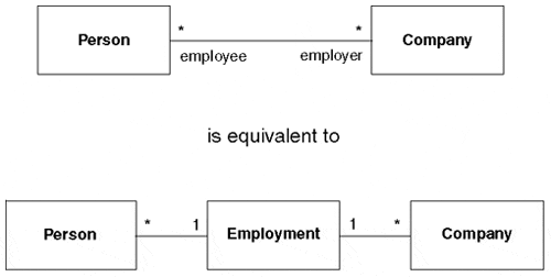
| SOLUTION | Transform the many-to-many association between two classes into a trio of classes by creating an intermediary class with two one-to-many relationships (see Figure 5.4). The name of the intermediary class should describe the type of relationship being captured. |
| RESULTING CONTEXT | A UML model with two classes linked by an intermediary class that has a one-to-many relationship to each of the first two classes. The resulting trio of classes will match the relational model, be easier to implement, and provide a richer way to capture the details of the relationship. |
| DISCUSSION | Many-to-many relationships look deceptively simple to the modeler and even seem to make intuitive sense: Many people can have accounts at many banks and many Web pages can be stored on many computers. Not only does an intermediary class provide additional flexibility in representing the many-to-many relationship faithfully, but also the construct is better supported by many implementing technologies. And a complicated many-to-many relationship usually warrants the support of a full class to capture the semantics. |
| This is an old and hoary concern of modelers since at least the dawn of relational modeling. Fortunately, the solution that makes sense in an object-oriented environment is also the proven one that worked in the relational world. So, the proven solution provides a convenient bridge between the modeling technologies as well as pointing to an implementation approach that has demonstrated effectiveness. | |
| The Many-To-Many Class Trio solution relies on the fact that the many-to-many relationship between two classes is logically equivalent to having an intermediary class with a one-to-many association going to each of the two primary classes. The intermediary class provides many advantages in elaborating and managing a many-to-many relationship: An intermediary object exists for each association between the two primary classes. | |
| This allows attributes and methods to be added to the relationship, such as a date range to the Employment class in the previous example. The multiplicity can be tweaked on either side of the intermediary class to more precisely define the exact nature of the relationship. For example, the multiplicities on the left side of the Employment class in the example could be changed from many-to-one to many-to-one to reflect the fact that a person many be unemployed or have only a single job at a time. The intermediary class is often better than using an association class to solve the many-to-many problem because it permits a greater level of control over the multiplicities, and the intermediary class does not constrain the number of instances of the same association between classes like the association class does. |
Figure 5.4. Modeling a many-to-many association.
5.8 MODEL THE SEAMS
| PROBLEM | How to identify and document the "seams" or boundaries between independent components in a system. |
| CONTEXT | A model of a component-based system. |
| FORCES |
|
| SOLUTION | Identify and model the interface dependencies in the system. The classes and components that are tightly coupled when compared to other groups of classes and components are good candidates. In general, the seams between the components of a system can be found and modeled by identifying all the interfaces they expose and the interfaces they use. |
| For each class or component, clearly identify the interfaces it uses (imports) and the interfaces it provides to others (exports). Model the interfaces imported using the dependency relationship and the exporting of interfaces using the realization relationship. The UML interface notation (the lollipop icon) is equivalent to the dependency relationship on an interface-stereotyped class. See Figure 5.5, which shows a stock trader component with the interface that it provides and the interfaces that it is dependent on. Figure 5.5. Clearly identified seams.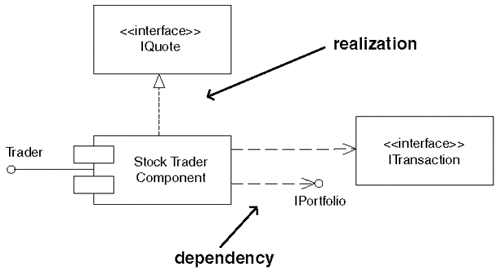 | |
| RESULTING CONTEXT | A component-based system model that has clearly identified "seams" around the components, using dependency and realization relationships between the interfaces. By using Model the Seams, the key aspects of component-based development are sustained, including plugable reuse, interoperability standardization, and the enforcement of independent units of configuration control. |
| DISCUSSION | Any non-trivial software is a maze of classes, components, and UML relationships. In a component-based development environment, the advantages of components are lost when the boundaries between components are blurred and the relationships between them imprecisely specified. By modeling the seams between the components that collaborate together to create a system, the modeler keeps the identities and semantics of the components in sharp relief. This emphasis on boundary is a reflection of a central theme in component-based development: interface/implementation separation. |
| The overriding goal in Model the Seams is to identify the components on both sides of an interface. By doing this, the modeler completely decouples the component, thereby providing a complete conception of how to provide support for the component (in terms of the interfaces it requires) or even to completely replace the component. |
5.9 PACKAGING PARTITIONS
| PROBLEM | Organizing the elements of a UML model based on a common guiding principle. |
| CONTEXT | The model of a distributed software system based on a multi-tiered architecture that divides the responsibilities of the system into distributed partitions. |
| FORCES |
|
| SOLUTION | One package per tier or partition; that is, organize the model elements of the distributed system by providing packages for each major partition or tier in the system. The packages are linked by defined dependency relationships between elements that communicate across the partition boundaries. For example, a common partitioning scheme for tiered systems is to isolate the presentation services (user interface tier) from the application logic (business service tier) and to keep access of information in a third tier (data service tier). Figure 5.6 shows one possible way to organize these three partitions using UML packages. Figure 5.6. Modeling elements into partition packages.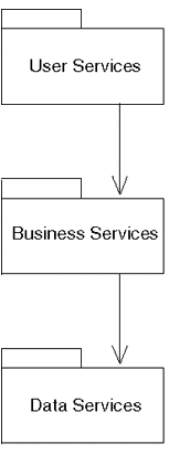 |
| RESULTING CONTEXT | A UML model that reflects the logical or physical distributed structure of the system. |
| DISCUSSION | The notion of packages in UML is purely organizational; a package itself is not directly realized in the implementation. By using packages to enforce multi-tier architecture, however, a model enforces system partitioning by preventing elements in different partitions from intermixing in ways they shouldn't. Using partitions-as-packages to organize the elements of a distributed system encourages loose coupling, reinforcing the distributed nature of the system. |
| Care should be taken to organize package elements into partitions so that visibility (via dependency relationships) is carefully exposed while unnecessary implementation detail is hidden from other partitions. | |
| Typically, each partition is constructed as a separate unit for configuration and construction purposes. Each partition package can vary independently, and it can be checked in and out of the model independently by each team responsible for it. |
5.10 LET THE TOOLS DO THE WORK
| PROBLEM | A modeler can easily be overwhelmed by the detail and prevented from focusing on the job at hand. How can this be resolved? |
| CONTEXT | Creating models using a software tool. |
| FORCES |
|
| SOLUTION | Always let the tool do as much of the UML modeling work as possible. Rely on the tool for routine and repetitive tasks. However, don't let the tool perform a particular modeling task if the results are poor or if more rework has to be done than would result by doing it by hand. |
| As a rule of thumb, and if your modeling tool supports it, always let the tool do the following work, as outlined in Table 5.1. |
| Type | Description |
|---|---|
| Model enforcement | Element renaming and deleting, element search (and replace), and completeness checking. Example: Using the tool to rename a class and having it change in every diagram in which the class appears. Anti-example: Changing the name of a package and then having to visit each package, importing it and manually changing the reference. |
| UML enforcement | Making sure that the model adheres to the UML meta-model is the one key role of a good modeling tool. Checking that a model is expressed in proper UML is a continuous validation process performed by the modeling tool. Example: Making sure that a class doesn't inherit from itself or that the same identifier doesn't appear more than once in the same namespace. |
| Code generation | Realizing the model into executable code. Example: Converting a design model into Java by using information stored in tagged values associated with each design model element. |
| Reverse engineering | Converting program source code into a UML model. Example: Taking the source code for a component written in C++ and generating a UML model that reflects the structure of the component. |
| Configuration management | Keeping track of the changes and releases of a UML model. Example: A tool supporting configuration management allows the changes made by multiple modelers to be reconciled and merged into a single change and checked back in to the model. |
| Wizards | These are interactive guided tasks through which the tool assists the modeler in a standardized repetitive task by doing most of the tedious work automatically. Example: A wizard that guides the modeler through the process of making a UML class adhere to a component standard, such as COM or CORBA. |
| Scripting | Tasks that are repetitive but time-consuming should be codified into scripts that can perform the work automatically and quickly. Parameters can be passed to the scripts to direct the work. In general, any recurring task that occurs on a weekly basis or more frequently and takes longer than 5 10 minutes is a good candidate for scripting. |
| Modeling "helpers" | Automated routines that help the modeler work more quickly and accurately. They include element name auto-completion when typing, diagram auto-arrangement, hierarchical model browsers, model element drag and drop, and so on. Example: when dragging a class onto a diagram that contains another class that already has a relationship with the first, a good modeling tool will ask whether the pre-existing relationships should be shown or elided. |
| RESULTING CONTEXT | A modeling environment that capitalizes on the modeler's unique capabilities by reducing the amount of time spend on menial and repetitive tasks. |
| DISCUSSION | Creating and managing UML models involves managing a large number of factors simultaneously: checking the UML syntax, adhering to modeling rules, following internal and external modeling standards, enforcing the semantics of the model itself, and so on. |
| Managing the model minutiae and helping the modeler perform routine tasks is one essential role of a good tool. The amount of manual work required to manage a non-trivial model is very considerable and is in direct proportion to the size of the model. The larger a model is, the larger the web of interdependencies that will complicate manageability. By letting the modeler focus on key issues that only he can resolve, the tool can relieve its user from the cost of dealing with issues that can be taken care of by the tool itself. The tool can also perform many other tasks through scripts that would normally cut into the modeler's valuable time. |
5.11 OPAQUE PACKAGES
| PROBLEM | How can the modeler ensure that clients will reference elements inside a package appropriately? How is loose-coupling through well-defined interfaces best achieved? And most importantly, how can this information be communicated via UML as well as enforced in practice? |
| CONTEXT | A UML model consisting of services decomposed into packages. |
| FORCES |
|
| SOLUTION | Make packages as opaque as possible by reducing the visibility of members of the package to private or protected. Make only essential elements public such as interfaces, facades, bridges, proxies, and so on. When displaying packages icons in diagrams, be sure to consistently display only the public elements inside them. This will uniformly communicate a clear sense of what is directly usable in the package and what is hidden implementation information. If protected or private elements must be shown, use a color/shading scheme for the package elements that shows what is visible and what isn't. Figure 5.7 shows a package containing public and private elements that use a color scheme. The shading shows which classes are not visible externally to the package. Order Processing is able to depend on the Customer package only through the Customer class. Figure 5.7. An opaque package with its single publicly exported class: Customer.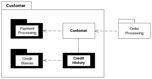 |
| RESULTING CONTEXT | A UML model with packages whose contents are largely opaque to the result of the model. Only the elements designed to interact with the rest of the model will be designated as publicly accessible. |
| DISCUSSION | The indiscriminant importing of package elements creates unwanted dependencies and tight coupling. Package access control is one of the key mechanisms provided by the UML for controlling dependencies between elements. Anything made private within a package cannot be referenced outside of it, even if the package is imported. |
| Two key factors must be present to ensure that opaque packages are successful in controlling dependencies: | |
|
EAN: 2147483647
Pages: 100