What Can FreeHand Do for You?
|
| < Day Day Up > |
|
This section describes a few of the types of projects for which FreeHand is extremely well suited.
Basic FreeHand Tools panel
You use several tools to draw with in FreeHand. No single tool is more valuable than another tool; instead, each tool does a specific type of work. The Pen or Bezigon tools can make straight lines, but if all you're going to do is draw straight lines, the Line tool is a better choice for the job. When you work on a drawing or layout in FreeHand, you will use many tools, and the more you learn about each tool, the easier your work will be. The default Tools panel is broken into two main groups, with the first group having four sections. You can change the orientation of the Tools panel to a single or double horizontal or vertical row of tools and place anywhere on your monitor. It rides above the entire document, but beneath the top menu bar. Some tools have a mark in the top-right corner of their icon. Double-click these tools to bring up a dialog box to modify settings for that particular tool.
| Note | You can customize the tool bar and menu bar by going to Windows ® Toolbars ® Customize. When this window is active, you can drag tools onto or off of any of the bars, or relocate them to suit your preferences. |
Before learning about the various tools, I suggest that you enable sounds in FreeHand if you work on a Mac (sounds are unavailable on Windows computers), unless you're working in an environment where the clicking and ticking from the program might annoy others. In the Edit ® Preferences panel, you can enable sounds for Snap To Grid, Snap To Point, Snap To (horizontal or vertical) Guide, and Snap To Path-Guide. This makes it really easy to know exactly where a point is going to be placed, or that you've gotten an object right where you want it to be. At times it will sound like you've got a high level of radiation coming out of your computer, but I find the sounds invaluable.
Selection tools
Selection is the name of the game. Arrow selection tools select any object or block of text that is not locked or on a locked layer. By using specific points on an object or bounding box, you can change the size or shape of most objects with these tools. The Text tool is the oddball in this section of tools, as it only works on text, but the other tools work on everything in a FreeHand document. Keyboard shortcuts are in parentheses after the tool's name. If there is no shortcut, you can usually add one in the Edit ® Keyboard Shortcut menu.
The Pointer tool (V or 0 [zero])
![]() The most often-used selection tool is the solid or black arrow, called the Pointer. If an object is filled, you can select the object by clicking anywhere within its boundaries. If it is not filled, you must click the Pointer directly on the stroke to select it. You can change the Pick Distance in the Edit ® Preferences panel. The smaller the number (in pixels) you input in the field, the closer you must be to the object before you can select it. The default is three pixels, and is usually an ample amount.
The most often-used selection tool is the solid or black arrow, called the Pointer. If an object is filled, you can select the object by clicking anywhere within its boundaries. If it is not filled, you must click the Pointer directly on the stroke to select it. You can change the Pick Distance in the Edit ® Preferences panel. The smaller the number (in pixels) you input in the field, the closer you must be to the object before you can select it. The default is three pixels, and is usually an ample amount.
If you need to select an odd-shaped object or many objects at once, click and drag a marquee (use the pointer to drag a selection) around the objects or points. Virtually everything enclosed within the marquee will be selected. Dragging the Pointer over a grouped object doesn't select the group or parts of it unless the Alt (Option) key is pressed. To select an entire group, object, or block of text by marquee-selecting, you must completely encompass the object.
You can change any tool into the Pointer tool when necessary by holding down the Control (Command) key. Release the modifier key to revert to the original tool. Clicking the Pointer tool anywhere on the page or pasteboard (not on an object) deselects anything that is selected.
| Note | Double-click the Pointer tool in the toolbox to open the Contact Sensitive window, which is turned off by default. If you turn it on, you don't have to surround an entire object to select it. Just dragging the cursor over a section of an object select that objects — without the extra effort of clicking (I know all that clicking sure tires me out). The Contact Sensitive window is available for the Subselect and Lasso tools, as well. Just drag the cursor over part of any object or group of objects to select them. If you happen to surround any points, they become actively selected; just crossing into a text block selects the block itself. |
| On the CD-ROM | On the CD in the Movies folder is a movie named Contact Sensitive.mov. |
The Subselect tool (A or 1)
![]() This is the open or hollow arrow tool, and is new to FreeHand 10. Use this tool to select objects that are in back of other objects, either on the same or different layers. (If you have the Pointer tool selected, you can achieve the same effect by holding down the Alt (Option) key.) The Subselect tool can also be used to modify the shape of a path by selecting a segment of the path between two points and dragging the path. The control handles of the points on each side of the segment move toward or away from the center of the segment as you drag the cursor.
This is the open or hollow arrow tool, and is new to FreeHand 10. Use this tool to select objects that are in back of other objects, either on the same or different layers. (If you have the Pointer tool selected, you can achieve the same effect by holding down the Alt (Option) key.) The Subselect tool can also be used to modify the shape of a path by selecting a segment of the path between two points and dragging the path. The control handles of the points on each side of the segment move toward or away from the center of the segment as you drag the cursor.
The Page tool (no keyboard shortcut)
![]() This tool selects an entire page with a single mouse-click. The page can then be moved around the pasteboard to align with other pages. If you click Delete, the page is deleted; you receive a warning that there are elements on the page, and you must decide to delete the objects or cancel. When you have Snap To Grid enabled (in the View menu), you can align multiple pages. You can quickly duplicate a page or range of pages by selecting them with the Page tool, holding down the Alt (Option) key, and dragging the duplicate pages to a new location. The engineering staff didn't want to take a chance that you would delete several pages of work in a single mouse-click, so you can only delete one page at a time with this tool.
This tool selects an entire page with a single mouse-click. The page can then be moved around the pasteboard to align with other pages. If you click Delete, the page is deleted; you receive a warning that there are elements on the page, and you must decide to delete the objects or cancel. When you have Snap To Grid enabled (in the View menu), you can align multiple pages. You can quickly duplicate a page or range of pages by selecting them with the Page tool, holding down the Alt (Option) key, and dragging the duplicate pages to a new location. The engineering staff didn't want to take a chance that you would delete several pages of work in a single mouse-click, so you can only delete one page at a time with this tool.
The Lasso tool (L)
![]() Use the Lasso to select individual points in an ungrouped object or objects. This tool is useful for selecting points that are very close together — a high zoom level helps, too.
Use the Lasso to select individual points in an ungrouped object or objects. This tool is useful for selecting points that are very close together — a high zoom level helps, too.
The Eyedropper tool (no keyboard shortcut available)
![]() In its basic sense, the Eyedropper is used to color objects. Click the Eyedropper in the color well, the Swatches panel, the Mixer or Tints panels, and drag the little box onto whatever you want colored. However, that's just as easily done with the Pointer tool. A better use of the Eyedropper is to select color from other objects on the page, and drag the color onto an object you want to have the same color. The Eyedropper tool can perform different functions when modifier keys are used. (These modifiers do not work with blocks of live text.) Table 6-1 lists the modifiers and their corresponding functions.
In its basic sense, the Eyedropper is used to color objects. Click the Eyedropper in the color well, the Swatches panel, the Mixer or Tints panels, and drag the little box onto whatever you want colored. However, that's just as easily done with the Pointer tool. A better use of the Eyedropper is to select color from other objects on the page, and drag the color onto an object you want to have the same color. The Eyedropper tool can perform different functions when modifier keys are used. (These modifiers do not work with blocks of live text.) Table 6-1 lists the modifiers and their corresponding functions.
| Modifier | Function |
|---|---|
| Control (Command) | Changes color of stroke only. |
| Shift | Changes color of fill only. |
| Alt (Option) | Radial fill centered on location of pointer at mouse release. |
| Alt+Control (Option+Command) | Contour gradient fill. |
| Command+Control (Mac) | Linear gradient, experiment for angle and direction of gradient. Gradient tends to start nearest the vertical or horizontal edge or a corner of the object, creating a vertical, horizontal, or diagonal gradient. |
The Eyedropper can also be used to choose a color within a gradient. This is extremely useful if you're trying to make another object blend seamlessly into a gradient.
The Text tool (T)
![]() As previously mentioned, the Text tool works only with text. Conversely, the Pointer tool becomes the Text tool on occasion. That occasion occurs when you double-click a block of text with the Pointer tool. Actually, triple-clicking a block of text usually turns the Pointer into the Text tool. But at times, all that clicking will add the Transform handles to the block of text, and the third click may move or rotate the block of text — it's a scary thought, but it happens now and then. You're better off selecting the block of text and then double-clicking directly on a line of text.
As previously mentioned, the Text tool works only with text. Conversely, the Pointer tool becomes the Text tool on occasion. That occasion occurs when you double-click a block of text with the Pointer tool. Actually, triple-clicking a block of text usually turns the Pointer into the Text tool. But at times, all that clicking will add the Transform handles to the block of text, and the third click may move or rotate the block of text — it's a scary thought, but it happens now and then. You're better off selecting the block of text and then double-clicking directly on a line of text.
You can just click the Text tool in the Tools panel. No matter how you get there, you're ready to set type. You can start typing in a couple different ways. The way you choose to proceed depends on what you want to do. If you want to set a quick line of text to print out and hand to your boss, such as, "I QUIT!" you can simply click the Text tool in the middle of the page and start typing. On the other hand, if you want to write a formal resignation, you can drag a text block of a specific size and shape, just as you would if you were drawing a rectangle. As you begin to type, your words fill the text block, depending on the various attributes and preferences you have set for the program.
| Cross-Reference | For further information on setting attributes and preferences, see Chapter 9, where type is covered in detail. |
When you choose the Pointer tool and you click a text block, the text block is treated as an object. If you choose the Text tool click in a text block, and select or double-click the text, the selection is treated as text, and not as an object. This can be a tough concept to get through to people who are new to the program. For example, if you select a block of 72-point text with the Pointer tool and choose an 8-point red stroke and a black fill, your block of text becomes a black rectangle surrounded by a thick red stroke. Conversely, select the text itself by dragging the Text tool over it and highlighting it. Then choose the same stroke and fill. Your letters will be black and be surrounded by a red stroke.
| Note | The red stroke described in the preceding paragraph is divided in half: four points of the stroke will be inside the letterform, and four points of the stroke's width will lie outside the letterform. To preserve the shape of the letters, you need to create a clone of the letters — without a stroke to them — and place it in front of the stroked text. |
The Text tool changes to the Pointer tool when the cursor is moved outside the text block. This is a wonderful, but sometimes confusing, process, and it does give cause for irritation if you want to begin typing a new text block. To continue typing, you must select the Text tool again.
Drawing tools
The four basic drawing tools in FreeHand are the Pen, Bezigon, Pencil, and Line. The first two create paths by the placement of individual points; Line and Pencil work differently. Again, default keyboard shortcuts are in parentheses, but you can change them.
The Pen tool (P)
![]() This is the most used tool when I'm at work. Until FreeHand version 9, the Pen tool worked predictably, but there seems to be some confusion as to what happened when FreeHand 10 was released — the Pen tool changed. Long-time users went crazy because what they expected to happen didn't, and the unexpected happened constantly.
This is the most used tool when I'm at work. Until FreeHand version 9, the Pen tool worked predictably, but there seems to be some confusion as to what happened when FreeHand 10 was released — the Pen tool changed. Long-time users went crazy because what they expected to happen didn't, and the unexpected happened constantly.
That said, the new and improved Pen tool works — it just works differently. Smart Cursors are tiny additions to the tool icon that tell you what the Pen or Bezigon tool is up to at a particular time. In no particular order, here's a list of what the new tool does. The Bezigon tool's icons employ the same attributes, but the tool has its own way of placing points.
-
Pen tool with no "smart cursor" icons, just the Pen icon — The next mouse click begins a path.
-
Pen tool with open circle — This pen point indicates that you will close a path with the next mouse click.
-
Pen tool with carat — Present point retracts the handle that would control the curve of the next path segment with the next mouse click. Note that a double-click doesn't remove the handle extending back to the previous point. The Carat icon over an existing point within a path retracts both control handles with the next mouse click.
-
Pen tool with plus sign — The next mouse click places a point between existing points on a path. It also shows up when you are about to place a point very close to the currently selected path. To keep either from happening, hold down the Shift key as you click. This may (or may not) conflict with your attempt to use the Shift key to constrain point placement to 45-degree alignment — proceed with caution! If this happens, the workaround is to place the new point as near as you can to where you want it, then move the point to its preferred location.
-
Pen tool with minus sign — The next mouse click withdraws both control handles of a point in the middle of a path if the point is a Curve or Connector point. It deletes the point under your cursor if the point is a Corner point. The path's curve will be determined by existing points on either side of the deleted point.
-
Pen tool with slash — The next mouse click makes the end point (the last point that has been placed) of an existing path live. Your subsequent click continues the path.
-
Pen tool with "X" — This cursor appears when you have an existing path selected, but the end point is not live. You begin a new path with this cursor, but if you move the cursor over other points in the selected path, the cursor changes to match the attributes of the existing point.
-
Pen tool with button-hole (circle with horizontal lines to the side) — Your next mouse click connects to an end path — the current path's, or another unselected path. Long-time FreeHand users, be wary!
In the Preferences panel, you can change the appearance of points in your documents. The FreeHand default point is a three-pixel solid square, and a selected point is a five-pixel open square. If you select the Show Solid Points option, points on a selected path are shown as three-pixel open squares, and the selected point is a solid five-pixel square. The points act exactly the same; they just appear differently. Try drawing with each of the preferences to see which works best for you.
As you place points, you can control the curvature of the preceding section of the path and the next section's curves at the same time. Visualizing what is happening helps if you think of the path as a flexible steel strap, similar to a long metal ruler. Each point controls the previous and next sections of the path — including the first point you place. A single mouse click with the Pen tool places a Corner point on the page. If you simply click the mouse elsewhere on the page, you get a straight path between the points. However, if you make that first click a click-and-drag movement, you apply a curve to the path that becomes apparent when you make the next mouse click. Depending on the location of the second point, you get something between a straight line and a severe curve.
| Note | The only way to get a handle on the way these drawing tools work is to use them. After a short learning curve, you'll discover that you know just how much to click and drag to achieve the curve you're after. Believe me, it's well worth the time to master the Pen and/or Bezigon tools by drawing intricate objects. |
If you want your path to complete a circuit and become what is called a Closed Path, you have a few alternatives to choose from. The easiest way is to make your last click on the first point you placed in the path. The cursor changes to have the little circle next to it, indicating that the path is closed. Another way to close a path is to go to the Object inspector and check the Closed box; the beginning and end points connect, with the path section reflecting any curves you applied on those points. Your last option is to install the Closed Path Xtra button on your toolbar or menu bar. Clicking that button closes the path.
| On the CD-ROM | In the Movies folder on the CD is a movie named pen_bezigon_movie.mov. |
The Bezigon tool (B, 8)
![]() For years, I ignored the Bezigon tool because it just seemed strange — but I've learned that it has a time and place, and now I use it frequently.
For years, I ignored the Bezigon tool because it just seemed strange — but I've learned that it has a time and place, and now I use it frequently.
What makes the Bezigon different than the Pen tool? It's the placement of the points as you draw. When you click the Pen tool on the page you get a Corner point. Click the Bezigon tool on the page and you also get a Corner point. However, say you're used to using click-and-drag to place a Curve point with the Pen tool. Using the Bezigon tool, a click-and-drag operation moves the point around the page. That's good and bad, depending on what you're trying to accomplish. If you want the point to stay put as you make a Curve point, you must hold down Alt (Option) as you click — forget about the dragging part for now. The Bezigon tool places a point with two Curve point control handles installed. Click the Bezigon on the page again and a curved path appears between the points. If you hold the Alt (Option) key down as you place that second path, you'll see that the new Curve point also has control handles on it. If you misplace the point (that is, put it in the wrong spot), keep the mouse down and move the point until it reaches the location you want.
I use the Bezigon tool to trace a curvy object or an ellipse that's at an odd angle. An ellipse that is horizontally or vertically oriented is easy enough to approximate with the Ellipse tool, but if the ellipse is at an angle, it's easier to draw with the Bezigon tool. Just place Curve points at the four points on the ellipse where the minor and major axes intersect the ellipse. The Bezigon tool usually does a great job of drawing the ellipse with only minor adjustments needed.
The Pencil tool (Y)
![]() If you're good with a mouse or trackball, you can draw directly on your FreeHand page with the Pencil tool. I consider myself pretty dexterous, but mastery of the Pencil tool with my trackball eludes me.
If you're good with a mouse or trackball, you can draw directly on your FreeHand page with the Pencil tool. I consider myself pretty dexterous, but mastery of the Pencil tool with my trackball eludes me.
When you draw with any of the Pencil tools, you trace a path on the page, and as you reach places in the path that mark a significant change in direction, the program places a Beziér point as you continue drawing your path. To speed up the drawing/redraw process on the monitor, you can have the program draw a dashed line as the temporary path. When you release the mouse, the path gains the visual effect you've chosen, according to the stroke type and its options.
Another option that you can use to your benefit is the amount of precision. Use the slider to choose a low number for loose, flowing lines with few points, or move to a higher number for a more precise rendering of the path you've drawn. The higher the number you choose, the more points FreeHand places on the path — sometimes it goes so far as to make printing difficult, so use your own judgment on a case-by-case basis.
The Pencil tool has variants that make using the tool interesting, fun, and invaluable. You find them by double-clicking the Pencil tool icon on the Tools panel. First, there's the Freehand version. With this option selected, you get a constant-weight stroke as you draw.
Then, there's the Variable Stroke, which is a natural for digital tablet users, and only slightly more complicated for mouse/trackball artists. To make a line thinner, press the left keyboard arrow; to make the line fatter, press the right keyboard arrow. The Pencil dialog box enables you to set a limit on the minimum and maximum line weights. Pressure sensitivity on a digital tablet makes this kind of drawing fun. There's another option in the dialog box that deals with overlapping strokes. If you select Auto Remove Overlap, the program converts the finished stroke into a compound path. This takes a bit of time for the computer to process, and also leaves you with compound path editing considerations. Compound paths are dealt with in the projects later in this book.
The other Pencil tool variation is the Calligraphic Pen. It's just like writing with a SpeedBall pen without the ink on your fingers. You have the option of setting minimum and maximum stroke width, and the angle of the pen. You can also choose to have a constant-width pen stroke.
The Line tool (N)
![]() Who says you can't draw a straight line without a ruler? The line tool only does one thing, but it does it very well. It places a starting point and an end point, with a straight path between the points. The line can be at any angle or length you choose, but it doesn't curve unless you go back with another tool (Pen or Bezigon) and change the starting or ending points. You can constrain the angle of the stroke to 45-degree increments by holding down the Shift key. You can also change the constraint angle to any angle you want by going to Modify ® Constrain, and entering an angle in the field. This is useful for drawing ellipses and moving elements at precise angles, as well as making straight lines.
Who says you can't draw a straight line without a ruler? The line tool only does one thing, but it does it very well. It places a starting point and an end point, with a straight path between the points. The line can be at any angle or length you choose, but it doesn't curve unless you go back with another tool (Pen or Bezigon) and change the starting or ending points. You can constrain the angle of the stroke to 45-degree increments by holding down the Shift key. You can also change the constraint angle to any angle you want by going to Modify ® Constrain, and entering an angle in the field. This is useful for drawing ellipses and moving elements at precise angles, as well as making straight lines.
To get more out of a straight line, just switch to the Pen, Bezigon, or Pencil tool. Then select the end point you want to extend, and continue drawing. The Line tool only places the beginning and end points, so it's tough to make a closed path unless you use the Join command.
Geometric drawing tools
Sometimes you want to draw simple things, like circles and squares. That's where this group of tools fits in. There really aren't many bells and whistles to them, but they're functional and elementary tools of the trade.
The Rectangle tool
![]() Use the Rectangle tool to draw four-sided boxes. Hold down the Shift key to constrain the rectangle to a square. Double-click the Rectangle tool icon to round the corners of the rectangle. Whichever unit of measure the document is currently set to will be the unit you use to mark the radius of the corners. If you're not conversant in points or picas but know inches really well, change the units setting at the bottom of the window before opening this dialog box — you can't change the units after this box is open.
Use the Rectangle tool to draw four-sided boxes. Hold down the Shift key to constrain the rectangle to a square. Double-click the Rectangle tool icon to round the corners of the rectangle. Whichever unit of measure the document is currently set to will be the unit you use to mark the radius of the corners. If you're not conversant in points or picas but know inches really well, change the units setting at the bottom of the window before opening this dialog box — you can't change the units after this box is open.
Click the mouse on the page and drag in any direction — the rectangle is drawn from wherever you clicked the mouse on the page. Press the Alt (Option) key to draw the rectangle from the center out. Press the Alt (Option) key and the Shift key draws a square from its center point out.
The Polygon tool
![]() Whereas the Rectangle tool builds rigid four-sided objects, the Polygon tool creates objects with any number of sides. The objects can be straight-sided polygons, such as an octagonal stop sign shape, or star-shaped. Double-click the tool's icon to bring up the Polygon dialog box. At the top of the box is a field and slider for adjusting the number of sides to the polygon. The slider itself has a maximum of 20 sides, but you can enter any number in the field. However, I won't guarantee that your computer won't crash if you get into the hundreds. A thumbnail box shows the shape you are developing as you modify the settings.
Whereas the Rectangle tool builds rigid four-sided objects, the Polygon tool creates objects with any number of sides. The objects can be straight-sided polygons, such as an octagonal stop sign shape, or star-shaped. Double-click the tool's icon to bring up the Polygon dialog box. At the top of the box is a field and slider for adjusting the number of sides to the polygon. The slider itself has a maximum of 20 sides, but you can enter any number in the field. However, I won't guarantee that your computer won't crash if you get into the hundreds. A thumbnail box shows the shape you are developing as you modify the settings.
The Shape choices are located beneath the information about the number of sides. You can have a polygon or a star. The Polygon choice has straight sides, and the more sides you add, the closer to a circle the polygon appears. The Star choice has interior and exterior points that are modifiable, as explained in the next section.
Star Points provides you with two adjustments: Automatic and Manual. An Automatic selection provides you with "badge shapes" for sheriffs and other police officers, until you reach 10 sides. After that, the polygon more or less turns into a circle with small points. By using the Manual option, however, you can make anything from a pointy starburst to a flat-edged polygon by moving the slider from Acute to Obtuse. The closer the slider is to Acute, the closer the inner star points come to the center of the polygon.
When you finish making adjustments to the polygon, click the OK button. The cursor changes to a crosshair. When you click the mouse and drag, the polygon is drawn from its center point. Modifier keys do not affect this tool, but you can manipulate the angle and dimensions of the polygon with any of the transformation tools.
The Ellipse tool
![]() Ellipses run the gamut from circles to thin "ovals," and anything in between. The Ellipse tool draws an ellipse from wherever you first touch the mouse to wherever you stop. To draw from the center out, hold down the Alt (Option) key, and to make a perfect circle, hold down the Shift key as you drag the mouse. Speaking of mice, you can draw Mickey Mouse with just a few click-and-drags of the Ellipse tool — if you're so inclined.
Ellipses run the gamut from circles to thin "ovals," and anything in between. The Ellipse tool draws an ellipse from wherever you first touch the mouse to wherever you stop. To draw from the center out, hold down the Alt (Option) key, and to make a perfect circle, hold down the Shift key as you drag the mouse. Speaking of mice, you can draw Mickey Mouse with just a few click-and-drags of the Ellipse tool — if you're so inclined.
The Spiral tool
![]() This tool is not as useful as the other tools that have been discussed, unless you need a spiral. Then it's invaluable. Double-click the Spiral tool icon to bring up its dialog box. You can choose between two types of spirals. The regular spiral (left icon button) provides an input field so that you can employ the exact number of lines or rings in the spiral. The proportional spiral (right icon button) enables you to determine the amount of growth between lines or rings in the spiral. Both types of spirals allow you to draw the spiral from the Center, the Edge, or the Corner of its bounding box. You can also choose from clockwise or counterclockwise spirals. See Figure 6-2 for a comparison of the two spiral types and their results.
This tool is not as useful as the other tools that have been discussed, unless you need a spiral. Then it's invaluable. Double-click the Spiral tool icon to bring up its dialog box. You can choose between two types of spirals. The regular spiral (left icon button) provides an input field so that you can employ the exact number of lines or rings in the spiral. The proportional spiral (right icon button) enables you to determine the amount of growth between lines or rings in the spiral. Both types of spirals allow you to draw the spiral from the Center, the Edge, or the Corner of its bounding box. You can also choose from clockwise or counterclockwise spirals. See Figure 6-2 for a comparison of the two spiral types and their results.
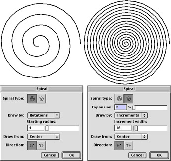
Figure 6-2: Spiral dialog boxes differ according to the type of spiral that you select.
In Figure 6-3, you can see an effect that would be tough to accomplish without the different spiral types. Using the specifications shown in Figure 6-2, two spirals were drawn from the same center point. Start with a horizontal and vertical set of guidelines; drag the first spiral (settings as shown in the left half of Figure 6-2) from the center line out to the right, while holding down the Shift key. Then bring up the Spiral dialog box again and change the specs to match the right side of Figure 6-2. Click the insertion point at the guideline intersection again (note that when the spiral is drawn, the first point is not at that intersection), and press Shift and drag the spiral to the right until the end points meet.
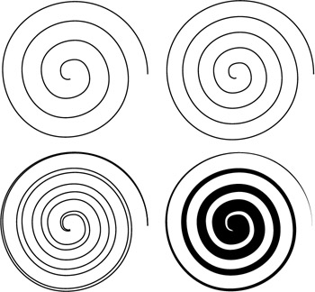
Figure 6-3: The development of a spiral
Select both spirals, and choose Modify ® Join. In the Object inspector, be sure that the path is closed. Then give the spiral a black fill and a stroke of None. You won't often need spirals, but a little experimentation can lead you to something more exciting than canned effects.
Transformation tools
The first thing to commit to memory about FreeHand transformations is that if you double-click an object while using the Pointer tool, you see a dotted-line box with eight black boxes in corners and in the centers of each side. These are called transformation handles. When the transform handles are in view, you can click and drag on any of the black boxes to scale, skew, or rotate your selection. The selection can be a single object, a grouped object, several objects or groups, or text blocks. Everything that is selected within the transformation handles is affected by your adjustments.
You can also open the Transform panel at this juncture, and select the various means of transformations. In this panel, you can enter specific increments of relocation, rotation, scale, skew, or reflection. You can also enter the center point of transformation in two ways: Enter the x/y coordinates if you know them, or click on the document. The mouse click causes the coordinates to be entered in their proper fields.
The Perspective tool
![]() This is probably the scariest tool in the FreeHand toolset, but it doesn't have to be. It's only scary because all the tools react just a bit differently, and some things don't work at all. Let's start with what does work, and why.
This is probably the scariest tool in the FreeHand toolset, but it doesn't have to be. It's only scary because all the tools react just a bit differently, and some things don't work at all. Let's start with what does work, and why.
Making the grid work
Draw an object or set some text that you want to see in perspective. Go to the View menu, and choose Perspective Grid ® Show. This places a one-point perspective grid on your document. Select the Perspective tool, and play a bit: Look at the cursor as you move it near a grid line. It turns into a vertical or horizontal triangle with a line. The triangle points to the grid that you are approaching. You can change the amount of perspective by clicking (when you have the triangle/line cursor) and dragging the mouse to move the vanishing point. All the lines that make up the grid are active, so it takes a bit of patience if you have a two- or three-point perspective and you happen to be zoomed in to a spot on the drawing that has multiple grids overlapping. The key is to watch the cursor, and look for the direction the triangle is pointing.
Attaching objects to the perspective grid
How do you put things in perspective? Keep the Perspective tool active, and select the object you want to have in perspective. For practice, put the object on the vertical face of the grid — lightly tap the left keyboard arrow and let go of the mouse. The object should appear in place on the grid. (If you only have one-point perspective active, press the right or left keyboard arrows to place the object on the active vertical face.) To place the object on the floor of the page, click the object again, tap the down keyboard arrow and release the mouse. If you select the object, you can move it around the grid and watch its perspective change.
Removing objects from the perspective grid
When you have the drawing the way you want it, select the objects that you're happy with and click View ® Perspective Grid ® Release With Perspective. Now the object is the same as any other FreeHand object and is not controlled by the Perspective Grid. In fact, if you select it with the Perspective tool and reapply the object to the grid, the distortion will be extremely dramatic — and basically senseless.
To remove an object from the grid so you can reapply it after making modifications, choose Remove Perspective. This places the object back on the pasteboard as a regular FreeHand object. Make your changes and reapply the object to the grid.
Adding more vanishing points
To get a second grid, in other words, two-point perspective, click View ® Perspective Grid ® Define Grids. In the dialog box, you can add the number of grids you want and change their colors. Adding grids has absolutely no effect on objects you already placed on a grid. If you want to have a second set of grids, open the Define Grids dialog box again, and select New. This lets you set up another grid that you can manipulate separately from the first grid. I advise you to set up a completely different color scheme and make a unique name for each grid you have just to keep your head in perspective. You can only see the grids one at a time; click View ® Perspective Grid, and at the very bottom of the pop-up menu you'll see a list of the grids you've made.
Changing object dimensions
Taking an object off the grid and putting it back on again is easy enough, but what if you just want to make it a tad larger or smaller? The solution is a bit of a mind-bender because of all the keys involved, but here is how it works. The changes work one pixel at a time. Select the object with the Perspective tool. Press the 2 key to enlarge height and width equally; for width alone, press the 4 key; for height only, use the 6 key. Notice that you use even-numbered keys for enlargement. To reduce an object's size, use the 1 key to reduce height and width by one pixel; use the 3 key for width alone, and the 5 key for height only.
Moving things around on the perspective grid
To move an object around the grid — up, down, left, right — use the Perspective tool. If you haven't moved the object with any other means, you'll get the effect you're after. If you want to constrain movement parallel to the grid, hold down the Shift key as you drag. To move an object and the grid that it's on, select the object, and move the cursor to a grid line (look for the triangle/line cursor). Hold down the Shift key and drag. To duplicate the grid — for instance, to make a ceiling out of the horizontal grid — hold down the Alt (Option) key as you drag the grid. If you have an object on a grid and you want to duplicate both the object and the grid, hold down Shift+ Alt (Shift+Option) as you drag, and a copy of the object will follow the grid in perspective.
Mirroring objects on the perspective grid
To make type (or an object) look as if it were applied to a glass store window that you are viewing from inside the store, select the object and press the Space Bar. Conversely, you can select the object; hold down the Shift key as you drag the grid from one extreme to another. The object mirrors itself as it passes through the vertical or horizontal plane, as seen in Figure 6-4.
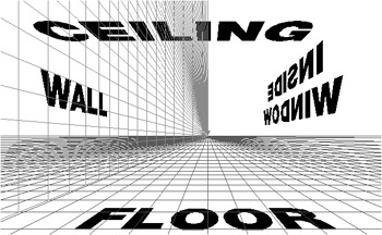
Figure 6-4: This illustration uses two sets of Perspective Grids; only one is visible.
Common situations with the Perspective Grid
Table 6-2 lists situations that commonly occur with the Perspective Grid and their solutions.
| Situation | Solution |
|---|---|
| You can't distort a bitmap by placing it on the Perspective Grid. | Import the bitmap, and outline it using an appropriate drawing tool (that is, if the bitmap has an irregular edge, use the Pen or Bezigon tool to make the outline). Apply the outline (not the bitmap) to the Perspective Grid. Then release the object from the grid and save it as a Photoshop or Illustrator EPS file. Open the bitmap file, and import the EPS file. Distort the bitmap to fit the EPS outline, and save the distortion, discarding the EPS outline. Back in FreeHand, import the distorted bitmap, but don't place it on the Perspective Grid, just place it as you would any other bitmap. |
| Text is impossible to edit on the Perspective Grid. | Just a misconception. Hold down the Opt (Command) or Alt (Control) keys as you double-click the text with the Pointer tool. The Text Editor box appears, and you can make any text changes there. Click Apply or OK, and the changes are effective and in perspective. Keep in mind, however, that once you release the text from the grid (Release With Perspective), you can't edit that text again. It is now a group of compound paths and can only be treated as such. |
| The perspective is too severe. | Move the vanishing points off the page. You have the entire pasteboard to work with. Note: If you have multiple pages, the vanishing points may not be usable if they happen to fall on an existing page — that page becomes active with its own set of perspective grids. |
| As things are moved around the Perspective Grid, they don't change perspective. | It's a matter of what you've done to the object since you placed it on the grid. If you place the object and then move it with any tool other than the Perspective tool (including keyboard arrow keys), you release the object from the grid. To move anything on the Perspective Grid, you must be in the Perspective tool. If you've goofed and moved something, don't be alarmed. Just select the Perspective tool again, and tap the appropriate arrow key to reattach the object to the grid. Then move it to the proper location. |
| The Perspective Grid doesn't work. Nothing you do makes stuff stick on the grid. | To apply an object to the grid, you must, first, select the Perspective Tool, and second, TAP the arrow key that applies to the correct grid. I repeat: TAP the key. If you hold the key down, nothing happens. Just hit it lightly and let it go and your object sticks to the grid as it should. Then you can move it around all you want. |
| Fill and stroke adjustments don't change color or size the way you'd expect. | With text, use the Opt (Command) or Alt (Control) keys while you double-click the text. Change attributes in the Text Editor. You can select objects with the Perspective or Pointer tools, and change their colors by selecting the Fill, Stroke, or Both boxes in the Swatches panel. |
| You can't seem to get the horizon to be at an angle. | It's a matter of perception. You can get it to an angle, but that angle is always perfectly flat — horizontal — and perpendicular to the vertical vanishing point. If it's necessary to have the horizon at an angle, you have to improvise by drawing within the grid, and then releasing the object(s) from the grid with perspective and rotating them. |
| The grid lies on top of your artwork, making it difficult to see what you're doing. | Turn off the grid's visibility. The Perspective Grid is active as long as you have the Perspective tool selected. |
| Note | The perspective of a stroke isn't affected when placed on the Perspective Grid; a box with a 12-point stroke turns into a trapezoid with a 12-point stroke if the box is applied to the Perspective Grid. To make the stroke have visible perspective, you must outline the path. In this case, you would use Xtras ® Path Operations ® Expand Stroke and type 12 in the Width field. When the object is attached to the Perspective Grid, the "stroke" (which is now a filled path or compound path) has the correct perspective. |
The Freeform tool
![]() Personally, I prefer to draw paths or manipulate paths one point and Beziér curve at a time. But, when you need to make organic shapes, such as a tree, seaweed, or a bowl of warm soup, you absolutely can't miss with the Freeform tool. It works with two different operational methods: Push/Pull, and Reshape Area. Both methods add or subtract points to the path as you use the tool on a path.
Personally, I prefer to draw paths or manipulate paths one point and Beziér curve at a time. But, when you need to make organic shapes, such as a tree, seaweed, or a bowl of warm soup, you absolutely can't miss with the Freeform tool. It works with two different operational methods: Push/Pull, and Reshape Area. Both methods add or subtract points to the path as you use the tool on a path.
You must double-click the Freeform tool to activate the dialog box that lets you to choose the tool type and various options. Figure 6-5 shows the dialog boxes for the two different Freeform tools. The cursor changes depending on which type of distortion you choose and the location of the cursor in relationship to the path itself. Use the Pressure settings if you have a digital tablet.
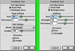
Figure 6-5: The type of Freeform tool settings are different for Push/Pull and Reshape Area.
Push/Pull
When you move the cursor around a path, notice how it changes. A small "o" next to the arrow means you are in the Push mode. The Push mode works by moving the shape of the path away from the cursor according to the size and precision values you enter. You enter the Size value in pixels from 1 to 1,000. A low number in the Precision setting adds fewer points to the changed path. A large circular cursor appears, showing the area you are distorting. To increase the size of the push pointer, press the right arrow key or right bracket (]) key; to decrease the pointer, press the left arrow key or left bracket ([) key.
If the cursor has a small "s" next to it, you're going to pull the path. The Pull setting enables you to choose a Bend option: By Length, or Between Points. By Length enables you to set the length of the segment (in pixels) that is affected. Between Points bends the path from the spot where the cursor touches the path and affects the control handles of the point on either side of the path segment if they're within the length setting.
You can constrain the pointer movement by holding down the Shift key. If you want to switch between the By Length and Between Points methods as you draw, hold down the Alt (Option) key then drag the mouse. If you start dragging and then hold down the Alt (Option) key, you clone the path.
Reshape Area
I use the Reshape Area tool when I need to draw little pointy things, which doesn't happen all that often, but this tool is a real time-saver when I use it. Just as with the Push/Pull option, you can set the size of the pointer from 1 to 1,000 pixels, and set the precision from 1 to 10 — with 10 being the highest precision and adding many points to the path. The Reshape Area tool also has a Strength setting. The higher the number you enter, the greater the distortion you make in the path.
Use the same keys to increase or decrease the size of the pointer as indicated for the Push/Pull tool. Use the up arrow key to increase the strength of the distortion, and the down arrow key to decrease distortion. The changes you make with the keys show up immediately in the size of the cursor.
Figure 6-6 shows the different types of drawings you can make with the Freeform tool. Both drawings started out as a vertical rectangle. The left side of the drawing was done completely with the Push/Pull tool (as set in Figure 6-5). The tree form on the right side of the figure was done entirely with the Reshape Area tool (with settings in Figure 6-5).
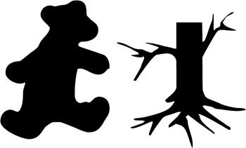
Figure 6-6: The Freeform tool has two different ways of working.
The Scale tool
![]() You'll use this tool often enough to warrant creating your own keyboard shortcut. When the tool is selected, the cursor turns into a star cluster. Wherever you click, the cursor (and hold or begin drawing) is the center point around which the scaling occurs. With that in mind, you can select an object and click anywhere on the page or pasteboard to enlarge or reduce the size of the object. Drag the cursor to the left or down to shrink an object; move the cursor right or up to enlarge it. To keep the change in size proportional, hold down the Shift key as you drag.
You'll use this tool often enough to warrant creating your own keyboard shortcut. When the tool is selected, the cursor turns into a star cluster. Wherever you click, the cursor (and hold or begin drawing) is the center point around which the scaling occurs. With that in mind, you can select an object and click anywhere on the page or pasteboard to enlarge or reduce the size of the object. Drag the cursor to the left or down to shrink an object; move the cursor right or up to enlarge it. To keep the change in size proportional, hold down the Shift key as you drag.
Certain attributes are affected when you use the Scale tool. Those attributes are found in the Transform panel. Double-click the Scale tool to open it. The three check boxes marked Contents, Fills, and Strokes usually cause the most confusion. Any of the three that are checked will be scaled along with the size of the object itself. A 12-point stroke is reduced to a 6-point stroke if the object is reduced about 50 percent, and it will be enlarged to about 18 points wide if the object is enlarged by about 50 percent. Uncheck this box, and the stroke remains 12 points wide at either size. With Contents checked, anything you have pasted inside an object is enlarged or reduced along with the object. Deselecting Contents leaves the pasted-inside content at its original size while the object gets bigger or smaller. The Fills box relates to tiled fills. Checking the box scales the tile; unchecking it leaves the tiled fill at the original size.
A neat option to the Scale transformation panel is the Copies box. If you enter a number in the Scale box, such as 150 percent, then type 4 in the Copies box and click Apply, the object you selected is cloned and enlarged 150 percent, then cloned and enlarged 150 percent, and again until the fourth iteration is complete. They will be nested concentrically — providing sort of a tunnel vision look. It's akin to the effect you get by making a blend between two different-sized objects, only with this method, the space between the shapes can be varied instead of regular.
The Scale tool isn't just for sizing — you can draw with it, too. Look at Figure 6-7. First I drew an eight-point star. Then I selected only the center points of the star, and clicked the Scale tool at about the ten o'clock position inside the center grouping. I dragged the mouse downward while I pressed Shift to make the points "smaller" — but in fact, it brought them closer together, creating a pretty neat bug splat. Then I selected the outer points and planted the Scale tool far to the right of the star and dragged to the right to "enlarge" the star. I didn't hold down the Shift key for this action, and all the points moved to the right of center, making this a powerful graphic that demands a "POW!" or "BLAM!" (You can create the same effect by making the star shape very acute in the Polygon panel. Then select only the inner points of the star and drag them to a new location. In FreeHand, there's always another way to do something.)
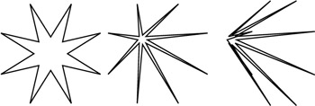
Figure 6-7: You can draw with the Polygon and Scale tools.
The Rotate tool
![]() The Rotate tool's options are few, but it does the job required. Select an object, choose the Rotate tool, and determine where you want the center of rotation to be. Click the mouse in that spot and drag. The center of the rotation is always wherever you click the mouse when you're using this tool. Double-click the tool's icon to bring up the Transform panel and Rotation attributes. You can enter a specific angle and x-y coordinates for the center of the rotation. Just as with the Scale transform panel, you can enter a number of copies in this panel and create some really quick artwork.
The Rotate tool's options are few, but it does the job required. Select an object, choose the Rotate tool, and determine where you want the center of rotation to be. Click the mouse in that spot and drag. The center of the rotation is always wherever you click the mouse when you're using this tool. Double-click the tool's icon to bring up the Transform panel and Rotation attributes. You can enter a specific angle and x-y coordinates for the center of the rotation. Just as with the Scale transform panel, you can enter a number of copies in this panel and create some really quick artwork.
The Mirror tool
![]() With some projects, this little gem can cut your drawing time in half, literally. If you are drawing a symmetrical object, just draw one half of it. Then make a clone of it and use the Mirror tool to flop the clone to the other side. (Conversely, you can double-click the Mirror tool, and enter 1 in the Copies field. Clicking the Mirror tool throws a clone of the original across the page for you.) Adjust the halves so their midpoints touch, and join the paths.
With some projects, this little gem can cut your drawing time in half, literally. If you are drawing a symmetrical object, just draw one half of it. Then make a clone of it and use the Mirror tool to flop the clone to the other side. (Conversely, you can double-click the Mirror tool, and enter 1 in the Copies field. Clicking the Mirror tool throws a clone of the original across the page for you.) Adjust the halves so their midpoints touch, and join the paths.
The Mirror tool can appear a little squirrelly with objects flying all around your page. Most mirroring is done from left to right or top to bottom. Holding the Shift key down as you drag the mouse constrains the mirrored image to 45-degree increments and calms down the screen activity.
The Skew tool
![]() When you want to put a different slant on things, this is the tool you need. Select an object and choose the Skew tool. Click the cursor somewhere near the object so you can have a better feel for what the tool is doing. Also, skewing is not restricted to simple parallel shifting of an object's sides. You can skew an object all over the drawing board. (It's similar to the 3-D Rotation Xtra in that respect.) If you just click and drag, the results are pretty haphazard, so hold down the Shift key to constrain the distortion to horizontal and vertical. When you drag the mouse up or down, skewing depends on the side of the object the mouse is clicked. Click the left side and drag up to make the right side of the object skew up. If you click the right side and drag up, the left side goes down. The side you drag from will remain in place. You get the same results, but have to think differently as you do it. The same concept works for left/right skewing.
When you want to put a different slant on things, this is the tool you need. Select an object and choose the Skew tool. Click the cursor somewhere near the object so you can have a better feel for what the tool is doing. Also, skewing is not restricted to simple parallel shifting of an object's sides. You can skew an object all over the drawing board. (It's similar to the 3-D Rotation Xtra in that respect.) If you just click and drag, the results are pretty haphazard, so hold down the Shift key to constrain the distortion to horizontal and vertical. When you drag the mouse up or down, skewing depends on the side of the object the mouse is clicked. Click the left side and drag up to make the right side of the object skew up. If you click the right side and drag up, the left side goes down. The side you drag from will remain in place. You get the same results, but have to think differently as you do it. The same concept works for left/right skewing.
| On the CD-ROM | On the CD in the Movies folder is a movie named skew tool.mov. |
Double-clicking the Skew tool icon brings up the Transform panel, where you can enter positive numbers in the Y and V text boxes to skew the object right or up; negative entries skew the selection left or down, respectively. You can enter copies to create clones of the object if you're using the panel for the skewing action.
The Trace tool
![]() The Trace tool is probably responsible for the most frustration to new FreeHand users. I think the problem lies in the name: People have the hope that they can click this tool and magically transform a full-color photo of Aunt Marge into a really cool drawing. Unfortunately, it doesn't work that way. The Trace tool looks a lot like the Magic Wand in Photoshop — and works in much the same way. However, whereas the Magic Wand selects contiguous colors within a particular color range, the Trace tool can select contiguous color and it can break the image into blocks of a defined color range — 2, 4, 8, 16, 24, 32, 64, 128, and 256 colors — and outlines each contiguous color section. The left drawing in Figure 6-8 is an example of what the Trace tool does using 16 colors, and very high sensitivity settings. The art in the center is the same trace as in the grayscale rendering, except that the closed paths have no fills. More than likely, though, you'll be looking for the drawing on the right, which is pure vector drawing.
The Trace tool is probably responsible for the most frustration to new FreeHand users. I think the problem lies in the name: People have the hope that they can click this tool and magically transform a full-color photo of Aunt Marge into a really cool drawing. Unfortunately, it doesn't work that way. The Trace tool looks a lot like the Magic Wand in Photoshop — and works in much the same way. However, whereas the Magic Wand selects contiguous colors within a particular color range, the Trace tool can select contiguous color and it can break the image into blocks of a defined color range — 2, 4, 8, 16, 24, 32, 64, 128, and 256 colors — and outlines each contiguous color section. The left drawing in Figure 6-8 is an example of what the Trace tool does using 16 colors, and very high sensitivity settings. The art in the center is the same trace as in the grayscale rendering, except that the closed paths have no fills. More than likely, though, you'll be looking for the drawing on the right, which is pure vector drawing.
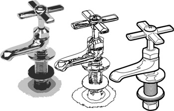
Figure 6-8: The faucet on the left is a 16-color trace to grayscale; the center drawing is the same trace without fills; and the right drawing was done with the Pen tool.
To utilize the Trace tool, start by double-clicking the tool in the Tools panel. This brings up the Trace Dialog box seen in Figure 6-9. Color settings are determined in the various fields: the number of colors; Grays or Colors; RGB (Red, Green, Blue) or CMYK (Cyan, Magenta, Yellow, Black); Low, Medium, or High Resolution; and Trace Foreground, Background, or All layers. The Path Conversion enables you to choose where to draw the path: Outline, Centerline, Centerline/Outline, or Outer Edge. Outline traces the outside edge of objects or colors and makes a closed, filled path. Choose Tight or Loose for the Path Overlap to determine how precise the tracing will be. If you choose Centerline, the Trace tool splits the middle of graphic strokes. Then you can apply Uniform (1-point) strokes to the line, or deselect Uniform to make a variable line weight. Figure 6-9 shows the difference between Uniform being selected or not. When you choose Centerline/Outline, the trace takes on the attributes of both Outline and Centerline, and you have the option of determining how wide a path must be before it is ignored. Any paths under the number of pixels you select (from 2 to 10 pixels) are left open. The last Path Conversion choice is Outer Edge. This selection creates a very tight clipping path to the graphic that has been traced. I use this frequently to make an object that I can fill with solid white (or a light gradient) and send to the back so the line work stands out on colored backgrounds.
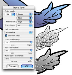
Figure 6-9: Trace tool options include the Uniform option. The original image is at the top, Uniform is selected in the middle, and at the bottom Uniform has been deselected.
Trace Conformity deals with just how tight you want the tracing to be to the original. Higher numbers make a tighter conformity to the object, and also place more points on the path. This also makes a larger file. Noise Tolerance is used as a means to get rid of stray pixels (noise) in a low-quality image. The higher the number you input here, the less noise you'll trace. Finally, the Wand Color Tolerance slider determines the sensitivity when selecting contiguous color ranges. A small number (0) selects a smaller number of colors; select wider ranges by using a higher number — up to 255.
All these settings are made in preparation for you to click and drag a selection box around the entire graphic, or a part of it. As with most drawing tools, holding down the Shift key constrains the selection to a square. The Trace tool works on type, bitmaps (color or grayscale), and vector graphics.
On the other hand, if you want to select particular colors in an image, such as the eyes, nostrils, and lips of a model for a special effect, use the Trace tool in a Magic Wand manner. Click an area that you want to trace. The Wand Color Tolerance comes into play here. If you end up with too much data in your selection, lower the tolerance until you get what you want. When you click the graphic, the program takes a second or two to make its selection, and then you'll see a row of marching red ants. If you want to add other areas of the image, Shift+click them. Use the same Shift-click to delete areas from a selection. When you're satisfied with your selection (this may take two or three attempts), click the wand on a selected area to open the Wand Options dialog box.
Choose to Trace Selection with the selections you set up in the Trace Dialog box, or Convert Selection Edge to trace the outer perimeter of your selection.
The Trace tool is often used to turn a bitmap into vector art for export to Flash or Fireworks. Be careful — depending on your settings, you can make a tracing that is many times larger than the original bitmap. You can also use the Trace tool operation to replace a graphic, which is very useful if you have a bitmap that you want to distort — for example by placing it on the Perspective Grid. The bitmap won't distort on the Perspective Grid, but if you do a nominal tracing of the bitmap, it will go onto the grid with no problems. For more information, see Table 6-2 above. Depending on its size (and importance), most viewers won't even notice that the image was posterized.
The Knife tool (K, 7)
![]() You can use the Knife tool to cut paths in a couple different ways. Double-click the Knife tool icon to open its dialog box, which presents you with two choices: Freehand and Straight. The Freehand knife works just like the Pencil tool: it draws a freeform cutting line wherever you drag the mouse. If you draw it across a selected path, the path is cut where the knife intersected it. Because all open paths must have an anchor point at each end, two points are created at the intersection. If you want to remove a section of the path, make another cut and deselect the path. Then select the section you want to remove, and cut or delete it. You have the option of creating a cut of a definite width, which is like using a paintbrush to wipe out a section of a path. All you have to do is adjust the slider in the dialog box to determine the cut's width. Another option is to leave the path cut, or Close Cut Paths. If you choose to close the paths, the path is where you want it, but an additional point (or points) is placed to one side of the path. When you have chosen a specific width to the cut, closing the cut path makes the path look as if you've taken a bite out of it. The tool places a point on each side of the width of the cut and continues pushing the path away from the cut, but in the shape of the cursor (which is a circle the diameter of the cut you selected). The last option you have is to have a Tight Fit to the cut. This option tries to maintain the location of the cut points on the path. Remember that you are cutting a Beziér curve, and that curve might not fall exactly where a point can be placed according to the program's math. So when you cut the path, the two end points may move slightly. If you're after precision, select both points and use the Align panel to center the points on each other vertically and horizontally.
You can use the Knife tool to cut paths in a couple different ways. Double-click the Knife tool icon to open its dialog box, which presents you with two choices: Freehand and Straight. The Freehand knife works just like the Pencil tool: it draws a freeform cutting line wherever you drag the mouse. If you draw it across a selected path, the path is cut where the knife intersected it. Because all open paths must have an anchor point at each end, two points are created at the intersection. If you want to remove a section of the path, make another cut and deselect the path. Then select the section you want to remove, and cut or delete it. You have the option of creating a cut of a definite width, which is like using a paintbrush to wipe out a section of a path. All you have to do is adjust the slider in the dialog box to determine the cut's width. Another option is to leave the path cut, or Close Cut Paths. If you choose to close the paths, the path is where you want it, but an additional point (or points) is placed to one side of the path. When you have chosen a specific width to the cut, closing the cut path makes the path look as if you've taken a bite out of it. The tool places a point on each side of the width of the cut and continues pushing the path away from the cut, but in the shape of the cursor (which is a circle the diameter of the cut you selected). The last option you have is to have a Tight Fit to the cut. This option tries to maintain the location of the cut points on the path. Remember that you are cutting a Beziér curve, and that curve might not fall exactly where a point can be placed according to the program's math. So when you cut the path, the two end points may move slightly. If you're after precision, select both points and use the Align panel to center the points on each other vertically and horizontally.
| On the CD-ROM | On the CD in the Movies folder is a movie named Knife tool.mov. |
Finally, there's the Straight knife action. Instead of drawing a wiggly line around your page, this selection lets you make a perfectly straight line, which facilitates placing the cut exactly where you want it. By its nature the Straight knife goes only from one side of an object to another, but if the object's path winds around (think of a dollar sign), the knife cuts the path every time it crosses the object. The Freehand knife can cut a path many times, even if you backtrack on the path. Holding down the Shift key while using the Straight knife constrains the direction of the cutting path to 45-degree increments, but the Shift key does absolutely nothing for the Freehand knife.
Viewing tools
![]() In discussing Viewing tools, I mean the tools you use to navigate around the FreeHand document. The Hand or Grabber tool, and the Zoom tool both lie near the bottom of the Tools panel.
In discussing Viewing tools, I mean the tools you use to navigate around the FreeHand document. The Hand or Grabber tool, and the Zoom tool both lie near the bottom of the Tools panel.
The Hand/Grabber tool (Spacebar)
FreeHand old-timers worked without this tool as a concept in a Tools panel until FreeHand 10. This latest version of the program places the Hand in the Tools panel. Select it and click somewhere in the FreeHand window. As you drag the mouse, you move the pasteboard in the window. Long-time users can still press the Spacebar to bring this tool up temporarily, instead of selecting the tool in the toolbox. No matter how you select the tool, you can cover a lot of screen real estate in a click/drag or two.
The Zoom tool
Zoom in or zoom out on the page with this tool (Spacebar+ Control (Command) or Spacebar+Control+Alt Spacebar+CommandOpt). The Zoom tool has been in the toolbox forever, but I find it much quicker to hold down the keyboard shortcuts: Spacebar+ Control (Control) to Zoom in, and add the Alt (Opt) key to Zoom out. Any trick that can save me a trip to a Tools panel or menu is something I like to learn and use. The point at which you click the cursor on the page becomes the center of the window when the view changes.
Color tools
Although these two items are just boxes, and not really "tools," they are located in the toolbox. They function much as the Swatches panel, but if you have two monitors, these two boxes are probably closer to your page than the Swatches panel is.
The Stroke and Fill color boxes
Both of these boxes work exactly the same way. One box applies to an object's stroke, and the other box determines the object's fill. The same explanation of their workings suffices for both. If the box has a color in it, any object you make (excepting text) has that color. The box with a red slash in it indicates a color of None for the stroke or fill. The color attributes of any object you select are indicated in these two boxes as well.
To change the color in the box — and therefore in present or future elements — you can drag a swatch of color from the Swatches panel, the Mixer panel, or the Tints panel. You can also use the Eyedropper tool to drag a color onto the color box. A more efficient method can be to click the box itself. A pop-up menu appears (see Figure 6-10) displaying either colors in the Swatches menu, or a grid of Web-safe color cubes. As you place the cursor over a color in the menu, the color's name and RGB or CMYK breakdown appears in a text field.
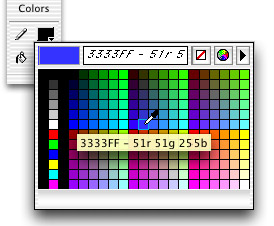
Figure 6-10: Flyout Stroke and Fill color menu
Next to the text field, a box with a red slash in it appears. Click this to give the element a color of None. To the right of that is a color wheel icon. When clicked, you get the Color Picker for further color choices. A PC shows a window with 56 color choices. A Mac has menus for CMYK, Crayons, HSV, Web Safe Colors, or RGB from which to choose. The color menu also has a pop-up Options menu that you activate by clicking the triangle in the top-right corner. When that menu is open, you can choose between Swatches and Color Cubes.
|
| < Day Day Up > |
|
EAN: 2147483647
Pages: 491