Creating Electrical Schematics
3 4
The Electrical Engineering solutions in Visio 2002 make it possible to create electrical and electronic schematic diagrams, as well as wiring diagrams, as Figure 27-8 shows. Among other things, you can draw integrated circuit and logic circuit schematics, general electrical diagrams (schematics, one-line, and wiring), industrial control system schematics, and printed circuit board drawings. The process for creating any of these diagram types is more or less the same—only the stencils from which you drag the shapes are different. Because all of the electrical engineering diagrams rely on default Visio shape and connection behavior, this section presents an overview of applicable techniques. All of the information presented in the first seven chapters of this book applies.
To start a new diagram based on one of the electrical engineering templates, choose File, New, Electrical Engineering, and then choose the template that sounds most like what you're trying to create. It doesn't particularly matter which template you choose; all create a standard, unscaled, letter-sized page. They differ primarily in the stencils that they open. Here are your choices:
- Basic Electrical. This template is used for one-line, wiring, and other general electrical schematics. It opens with the Fundamental Items, Qualifying Symbols, Semiconductors And Electron Tubes, Switches And Relays, and Transmission Paths stencils.
- Circuits And Logic. This template is used for integrated circuit and logic circuit schematics. It opens with the Analog And Digital Logic, Integrated Circuit Components, Terminals And Connectors, and Transmission Paths Stencils.
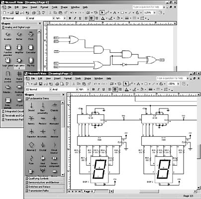
Figure 27-8. With the electrical engineering templates, you can create logic diagrams, circuit diagrams, and other schematics.
- Industrial Control Systems. This template is used for control system schematics. It opens with the Fundamental Items, Rotating Equip And Mech Functions, Switches And Relays, Terminals And Connectors, Transformers And Windings, and Transmission Paths stencils.
- Systems. This template is used for printed circuit boards. It opens the Composite Assemblies, Maintenance Symbols, Maps And Charts, Switches And Relays, Telecom Switch And Peripheral Equip, Terminals And Connectors, Transformers And Windings, Transmission Paths, and VHF-UHF-SHF stencils.
If there's a trick to working with the electrical engineering shapes, perhaps it's finding the one you want. Not only are there 15 different stencils with more than 400 shapes to choose from, individual shapes can often be configured to represent different symbols or settings, as Figure 27-9 shows. Right-click shapes to determine whether they include options. Visio uses custom properties to make these shapes configurable. If you dock the Custom Properties window on the screen, Visio displays a shape's properties in the window as you select the shape, which makes it easy to see which ones can be configured.
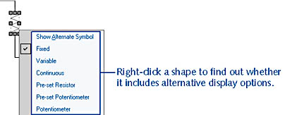
Figure 27-9. Many of the electrical, logical, and electronic shapes can be used to represent multiple symbols and settings, like this Resistor shape from the Fundamental Items stencil.
Connecting Electrical and Electronic Shapes
The efficient way to create a diagram that shows a lot of connections is to start with the fixed shapes and then connect them. For example, drag the logic gates onto the page, arrange and distribute them, and then use the Connector tool to connect them. Or start with resistors and capacitors, and then drag lines between them.
Use the Connector tool to connect components, as Figure 27-10 shows: select the Connector tool on the Standard toolbar, and then drag from a connection point on one shape to a connection point on another shape. Visio attaches the line to the shapes with point-to-point (or static) glue. When you move shapes, the connecting line may be rerouted, but the same two points stay connected.
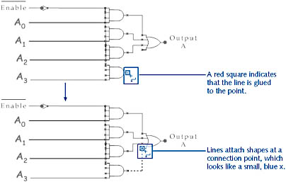
Figure 27-10. Because connector lines have a beginning and an end, use the Connector tool to drag in the direction you want the line to flow.
InsideOut
If you drag the endpoint of a connector toward the middle of a shape, a red box appears around the entire shape to indicate that shape-to-shape (or dynamic) glue is in effect—which is probably not what you want. With shape-to-shape glue, you can move components on the page, and Visio automatically reroutes the connector to the closest connection points between the two shapes. If your goal is to show the circuit at pin 2, you want to ensure you're gluing at points, not gluing entire shapes.
Another handy reason for using the Connector tool is that the resulting line includes a shortcut menu with options for rerouting, as Figure 27-11 shows. A connector can also imply direction. It draws a line with a beginning and an end—the square endpoints you see when you select it. To show directionality in your diagram, such as the flow of electricity from a junction to the ground, always drag from the initiating point to the terminating point, using the Connector tool.
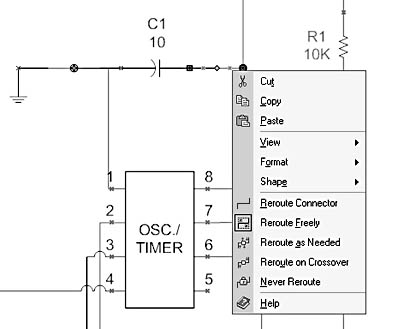
Figure 27-11. You can right-click lines drawn with the Connector tool to display a shortcut menu with commands for controlling the line's routing behavior.
The way Visio automatically reroutes lines in a drawing can be mysterious. The best advice is usually to try a routing option and see if it does what you want. If not, press Ctrl+Z to undo the results and try something else.
For details about layout and routing options, see "Laying Out Shapes Automatically."
Where Is the Netlist Generator?
Previous versions of Visio Technical included the Netlist Generator, an add-in that listed all the components in a circuit, the nodes to which each component was attached, and the value of each component. Sounds useful, but in practice, the information it produced was limited, and its output format was incompatible with most commonly used circuit simulation programs. The result is that Microsoft pulled the add-in from Visio Professional 2002. It's gone—but perhaps not forever. The goal is to create a new Netlist Generator, possibly for the next product release. So stay tuned.
In the meantime, you may be able to replicate some netlist-type functionality by creating a custom report definition. Using the Report Definition Wizard, you can generate a list of properties associated with shapes on the drawing page automatically, including width, height, and endpoints.
Tip - Connect Shapes as You Add Them
If it's okay not to connect shapes at specific points, you can quickly connect a series of components as you add them to the page. To do this, select the Connector tool, and then drag a shape onto the drawing page. With the shape selected, drag the next component onto the page. The shapes are automatically connected using shape-to-shape glue.
Labeling Components
The electrical engineering shapes rely primarily on Visio's default text-handling capabilities. That is, to add text to a shape, select the shape, and then type. You can control the position of the shape's text by dragging the control handle on the shape, as Figure 27-12 shows.
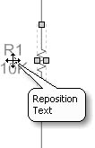
Figure 27-12. To move the label on a component, drag the control handle.
For details about formatting text, see "Formatting Text."
The quickest way to format labels is probably to edit the EE Normal style, which is applied to all the electrical engineering shapes. By editing the style, you can establish a consistent format for your shapes. To edit a style, choose Format, Define Styles, select the EE Normal style, and then use the Change options to specify different text formats.
For details about editing styles, see "Editing Existing Styles."
EAN: 2147483647
Pages: 211