Linking Shapes and Databases
3 4
Visio can link shape properties to database records with a two-way connection that you can keep up to date. In programmatic terms, the link is persistent, which means that after you set up the link between shapes and database records, the connection remains in effect as long as both the drawing file and database exist. When you change the value of linked shape properties, you can refresh the database with the values. Likewise, when the database changes, you can update shapes. Clearly, this functionality is a powerful way to tie drawings and data together. Your drawing file can become a dynamic catalog of information that accurately reflects the contents of a database. At a minimum, you can create a shape-to-database link to import values into custom property fields.
Linking Limitations
There are limits to what Visio can do when it creates a link between a shape and a database record. Be aware of the following limitations:
- String size. You cannot store ODBC strings larger than 64-KB characters in Visio cells and fields.
- Primary key type. You cannot specify a field of type SQL_TIMESTAMP as the primary key.
- Replication IDs. You cannot update replication IDs from an Access database.
- Timestamp fields. You cannot update Timestamp fields from an Informix database.
- Binary field size. You cannot store ODBC binary fields larger than 32 KB in Visio cells and fields.
Note
Visio stores numeric values as double floating-point numbers. If your database contains numbers with a large degree of precision, Visio stores them as approximate values.
Using the Link To Database Command
Follow these steps to link shape properties:
- Select the shapes you want to link, and then choose Tools, Macros, Visio Extras, Link To Database.
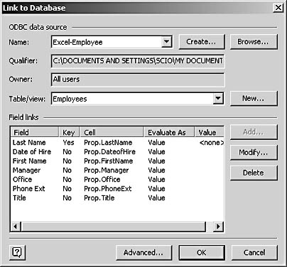
- In the Name list, select the ODBC data source that you want to connect to.
For details about creating a data source, see "Connecting to an ODBC Data Source."
If you select Excel Files, the Select Workbook dialog box appears. Locate the file (.xls) that you want to use, and then click OK.
- If your data source supports multiple databases, select the database you want in the Qualifier list box. To limit the number of tables that Visio displays, select the name of a database creator in the Owner list box.
Note
If your data source is Excel, Access, or another program that creates a single database, the Qualifier box displays the database name and the Owner box defaults to All Users. - In the Table/View list, select the table that contains the records and fields you want to link to. To list fields from a system table or alias name, click Advanced, select an option under Link To, and then click OK. To create a link and a new table, click New, define the options you want, and then click OK.
- To limit the number of fields that Visio links to shape properties, under Field Links, select a field in the Field column, and then click Delete.
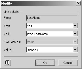
- To link a field to a different property or change the way Visio evaluates the database value, select the field, click Modify, make the changes you want, and then click OK.
InsideOut
In the Link To Database dialog box, make sure the field specified as Key (that is, the primary key) contains meaningful values in your data source. To change the field designated as the primary key, select a field, and then click Modify. In step 8, Visio displays the values of the primary key field in the Select Database Record box. It's simply easier to select a record based on a meaningful name (such as employee name, part type, room number, and so on) rather than an index or abstract ID number. - To link the database fields and shape properties, click OK.
- To associate a linked shape with a specific record, right-click the shape, and then choose Select Database Record. Or, if you added links to a master shape, drag the master onto the drawing page, and then choose Select Database Record.
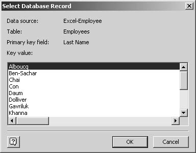
- In the Key Value list, select the record you want, and then click OK to add its values to the corresponding custom properties or ShapeSheet cells.
Linking Master Shapes
You can select any shape on the drawing page and link it to a database record, but you get a more efficient result when you link master shapes instead. Each shape or master shape must be linked individually, so setting up links can be a time-consuming process no matter what type of shape you link. However, the advantage of linking master shapes is that you can drag the master onto the page to create many instances of the shape, and each instance can be linked to a different record in the database.
Visio includes a sample diagram and stencil of linked master shapes that demonstrate this feature. They're installed by default in the C:\Program Files\Microsoft Office\Visio10\1033\Samples\Visio Extras folder. The Sample Database Shapes.vss stencil contains a variety of linked master shapes. For example, when you drag the Office Card shape onto the drawing page, Visio displays the Select Database Record dialog box, in which you can select an employee record. The Office Card shape has built-in intelligence that adds the value of the database record to text fields on the shape, as Figure 24-5 shows. The Sample Database Airplane Seating.vsd drawing in the same folder shows another example of linked shapes in a drawing that's worth exploring.
You can open a master for editing, and then use the Link To Database command to link it to a database record. Or you can link a shape on the drawing page and then drag it to a stencil to create a master that includes links. To add functionality similar to that of the office card shape, in which dragging the shape onto the page causes the Select Database Record dialog box to open, you must click the Advanced tab in the Link To Database dialog box and then select the Select Record check box under Shape Drop Event.
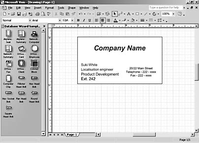
Figure 24-5. The shapes on the Sample Database Shapes stencil are linked to records in an Access database (Dbsample.mdb) stored in the same folder as the stencil.
Adding Shortcut Commands to Linked Shapes
By default, Visio adds commands to the shortcut menus for linked shapes so that you can more easily manage the database connection. When you use the Link To Database command, however, you can specify which actions and events you will be able to control from the shortcut menu. Action and event are Visio programming terms. An action in this context means a command that causes an action to occur, such as refreshing linked shapes. An event is simply something that happens, such as a user opening a drawing file. A drop event occurs when a shape is added to the page (copied and pasted or dragged from a stencil). In the Link To Shapes dialog box, you can click the Advanced button to display the Advanced dialog box, which contains these additional options, as Figure 24-6 shows.
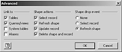
Figure 24-6. You can specify which shortcut commands Visio creates with the options under Shape Actions and Shape Drop Event in the Advanced dialog box.
You can specify the following actions:
- Select Record. With this command, you can associate a shape with a specific database record and add the record's values to the shape's properties.
- Refresh Shape. With this command, you can update the shape's property values based on the current database values.
- Update Record. With this command, you can write the shape's property values to the linked database record.
- Delete Shape And Record. With this command, you can delete a shape and the database record to which it is linked.
Troubleshooting
Copying a linked shape either copies the same link or doesn't copy any link.
If you want to be able to copy and paste linked shapes—with links intact—you must specify an option that's available only when you click Advanced in the Link To Database dialog box. In the Advanced dialog box, the Shape Drop Event options control what happens when a shape is added to a page either through copying and pasting or by dragging a master from a stencil. If you select the Select Record option, Visio will prompt you to select a database record when you copy and paste a linked shape. That way, you can associate copies of shapes with new records. By default, the Refresh Shape option is selected, which means that copies of shapes are refreshed with the latest data from the same database record unless Select Record is also selected.
You can specify the following drop events:
- None. When you add a new shape to the page, nothing happens.
- Select Record. When you drop or paste a shape, Visio displays the Select Database Record dialog box, in which you can select a specific database record to link the shape to.
- Refresh Shape. When you drop or paste a shape, Visio updates its link and refreshes property values based on the latest database information.
Linking to a New Table
If you want to create a table in your database and define its fields at the same time you link those fields to shape records, you can do so in the Link To Database dialog box. Instead of selecting a table in the Table/View box, click the New button to display the New dialog box, shown in Figure 24-7. Here, you can name a new table and identify its fields and their data types. Visio creates the table in your database and displays its fields in the Link To Database dialog box.
To create a new table, in the Table Name box type a name for the table that doesn't conflict with the names of other tables in the database. Then type the name of a field you want to include in the Name box, identify its data type in the Type box, and click Add. Make sure that at least one field is identified as a primary key, or Visio won't be able to refresh the link.
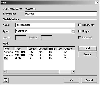
Figure 24-7. Rather than link to an existing table, you can create a new table in an existing database with the options in the New dialog box.
Understanding How a Visio Link Works
This section helps you understand exactly how Visio creates and stores the shape-to-database links that you create. After you link a shape to a database record, Visio creates a cell named User.ODBCConnection in the User-Defined Cells section of the ShapeSheet window. You can select a linked shape and then choose Window, Show ShapeSheet to see this cell and its contents, as Figure 24-8 shows.
Generating Shapes from a Database
The Link To Database command doesn't include one option that the Database Wizard does: the ability to generate new master shapes based on information contained in a database. This feature is particularly useful for organizations that maintain large databases of inventory or specification information. You can generate shapes that represent each type of part or each size of item in your database. However, to take full advantage of this option, you might want to design your own master shapes and then program them to respond to the database input.
To see how this feature works, experiment with the sample master shapes that are linked to the Dbsample.mdb database (C:\Program Files\Microsoft Office\Visio10\1033\Samples\Visio Extras\Sample Database Shapes.vss).
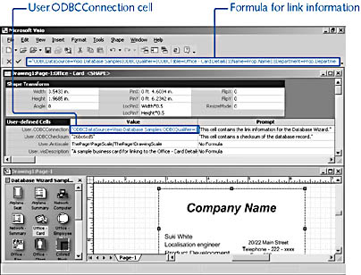
Figure 24-8. Visio stores the information about a shape-database link as a formula that specifies the primary key, field, and most recent value.
The formula in the User.ODBCConnection cell is a very long line of code that looks a lot more straightforward when you break each line at the vertical bar like this:
 ODBCDataSource=Visio Database Samples
ODBCQualifier=
ODBCTable=Office - Card Details
1
Name=Prop.Name
3
Department=Prop.Department=0
Extension=Prop.Extension=0
Title=Prop.Title=0
This example is taken from the Office Card shape on the Sample Database Shapes stencil. Here's what Visio records with each parameter:
- ODBCDataSource=<name>. This parameter stores the name of the data source used to link the shape. In the example, the data source is Visio Database Samples, which specified a table in an Access database.
- ODBCQualifier=<name>. For a data source that includes multiple databases, this parameter would specify the specific database. In the example, the Access data source doesn't support multiple databases, so the parameter doesn't include a value.
- ODBCTable=<name>. This parameter identifies the table in the database to which the shape is linked. In the example, the shape is linked to the Office-Card Details table.
- <Number>. This parameter shows the number of key fields that have been specified. In the example, only one key field is used. You can select multiple key fields when you link shapes using the Database Wizard rather than the Link To Shapes command.
- Name=<name>. This parameter identifies the custom property or ShapeSheet cell that stores the key field. In the example, the Prop.Name custom property is the key field.
- <Number>. This parameter identifies the number of fields that are linked to shape properties. In the example, three fields are linked. Each field is then described in the remaining parameters.
- <Field name>=<cell name>=<number>. Each of the remaining parameters identifies a specific field, the name of the cell where Visio stores its values (cells that represent custom properties are prefaced with "Prop."), and the manner in which Visio evaluates the current value of the property. In the example, the Title field is linked to the Prop.Title cell. The number 0 reflects the setting for the Evaluate As options and refers to a string. In programming terms, this number is a constant. Its possible values are shown in Table 24-1.
Table 24-1. Constants for Units of Measure
| Constant | Unit of Measure | Constant | Unit of Measure |
|---|---|---|---|
0 | String (text) | 66 | Feet |
1 | Formula | 68 | Miles |
32 | Nondimensional number | 69 | Centimeters |
33 | Percent | 70 | Millimeters |
40 | Dates | 71 | Meters |
50 | Points | 72 | Kilometers |
51 | Picas | 75 | Yards |
53 | Didots | 76 | Nautical miles |
54 | Ciceros | 81 | Degrees |
63 | Default page units | 83 | Radians |
64 | Default drawing units | 84 | Minutes (of an angle) |
65 | Inches | 85 | Seconds (of an angle) |
EAN: 2147483647
Pages: 211