Adding Building Services
3 4
After you've created a floor plan for a home, office, or industrial site, you can add services for the facility, as Figure 18-17 shows. Visio Professional provides the shapes and tools you need to create plans for HVAC (heating, ventilation, and air conditioning), plumbing, electrical, and security systems. If you have Visio Standard, the Office Layout template includes a few electrical shapes, but for the most part, the sections that follow apply only to Visio Professional.
It's beyond the scope of this book to describe best practices for designing these systems— the assumption is that you know more than the author about building architecture and services. However, the sections that follow can help you work most efficiently with the shapes. The key strategies to remember when working with these shapes are:
- Right-click shapes to display a shortcut menu that might contain shape options.
- Use the Custom Properties window to set shape specifications.
- Use the drawing's layers to organize different elements in your plan. All the building plan shapes are already assigned to layers.
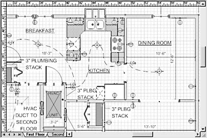
Figure 18-17. This home plan includes ductwork, plumbing, and electrical information.
The following sections tell you more specifically about how to use these techniques to customize your drawing, whether it's a floor plan you've created in Visio or a CAD drawing you've imported.
If you're planning services for an office, plant, or even a home, chances are good that you'll need to include a computer network. There are many different ways of configuring a network and just as many ways to diagram them. Both Visio Standard and Visio Professional include network shapes that you can add to a floor plan. For details, see Chapter 14, "Creating Network Diagrams."
Troubleshooting
When you add shapes to a floor plan, you accidentally move walls and other structural shapes.
Before you begin to add services or network shapes to a floor plan, lock the layers that make up the floor plan so that you don't move a wall accidentally, for example, when you're positioning an electrical outlet. There are two ways to lock layers depending on the type of floor plan you have:
- If you created the floor plan in Visio, choose View, Layer Properties, and then check the Lock column for any layer you want to protect.
- To lock a CAD drawing you've imported, right-click the drawing, and then choose <File Type> Object, Properties. For example, choose CAD Drawing Object, Properties or MicroStation DGN File Object, Properties. In the CAD Drawing Properties dialog box, select the Lock Position check box.
Adding HVAC Services to a Plan
Your floor plan can show the equipment and controls for what one company charmingly calls "indoor comfort systems," as Figure 18-18 shows. Visio includes shapes for designing the cooling, heating, and ventilating equipment and controls, from temperature sensors to water chillers. The Building Plan solutions folder includes two HVAC templates, one for creating control logic schematics and the other for ductwork and equipment.
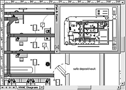
Figure 18-18. The return and supply ducts in this plan are color coded to indicate their use. The Pan & Zoom window makes it easy to see the entire drawing while you work closely on one segment.
The HVAC Control Logic Diagram template opens a scaled drawing page and the following stencils:
- HVAC Controls. This stencil provides a variety of sensors.
- HVAC Controls Equipment. This stencil includes shapes for ducts, fans, filters, pumps, and so on.
- Annotations. This stencil includes callout shapes for labeling the schematic.
The HVAC Plan template opens a scaled drawing page and these stencils:
- HVAC Equipment. This stencil includes shapes for pumps, condensers, and fans.
- HVAC Ductwork. This stencil contains a variety of duct shapes.
- Registers, Grills And Diffusers. This stencil includes standard inlet, outlet, and diffuser shapes.
- Drawing Tool Shapes. This stencil comes with geometric shapes for creating other objects.
The way you start working with these shapes depends on whether you want to add HVAC information to an existing floor plan or design from scratch. You have the following options:
- To insert HVAC information in a floor plan you created in Visio, open the floor plan, and then use the Open Stencil button on the Standard toolbar to open the HVAC stencils you need.
- To add HVAC information to a floor plan created in a CAD program, start in Visio by choosing File, New, Building Plan, and then select one of the two HVAC templates. Then insert the CAD drawing (choose Insert, CAD Drawing).
For details, see "Using a Floor Plan from a CAD Drawing", or refer to Chapter 17, "Using CAD Drawings in Visio."
- To start a new HVAC diagram from scratch, start Visio, choose File, New, Building Plan, and then choose the HVAC template you want.
You might find it most convenient when using HVAC shapes to keep the Custom Properties window docked on the drawing page. To display it, select View, Custom Properties Window. When you select a shape on the page, its configuration properties appear in this window. All of the built-in Visio control and equipment shapes include custom property fields. You can set specifications for shapes in this window, such as sensor type or voltage limits. You can also use any of the HVAC shapes to track other information as well, such as part number, manufacturer, model identifier or tag number, and so on. When you enter values for these properties, you can then generate reports or parts lists automatically (choose Tools, Report).
The shapes on the HVAC Controls Equipment template conform to the relevant standards for graphic symbols of the American Society of Heating, Refrigerating, and Air Conditioning Engineers, Inc. (ASHRAE). The primary concern of the ASHRAE is to set American standards. If you're designing plans for buildings outside of the United States, the standards vary.
Inserting Control Logic Schematics
You can design control logic schematics that show the equipment, wiring, and sensors used to control an HVAC system. Visio packs a lot of features in a few shapes. Don't be deceived if you don't see the exact control symbol you're looking for. Many of the shapes have a switchable configuration that you specify in the in the Custom Properties window (or a shape's Properties dialog box). For example, if the Custom Properties window is open, you can select a pressure sensor shape, and then select the type of control from the Type list as Figure 18-19 shows.
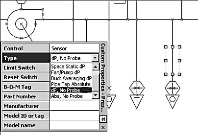
Figure 18-19. You can customize many HVAC shapes in the Custom Properties window. Click in a field to display a drop-down list.
Tip
To determine whether a shape property can be customized, click in a field of the Custom Properties window. A drop-down list of options appears for some properties, including Control, Type, Limit Switch, and Reset Switch.
If you're working in an existing floor plan, follow these steps to open the stencils you need to insert control logic symbols:
- Click the drop-down arrow on the Open Stencil button on the Standard toolbar to display the list of drawing types.
- Choose Building Plan, HVAC Controls.
- Repeat to open the HVAC Controls Equipment stencil.
- If you plan to annotate the diagram, click the Open Stencil button's drop-down arrow, and select Visio Extras, Annotations to open the Annotations stencil.
The HVAC shapes are designed to connect and stay glued, as Figure 18-20 shows. When you drag the endpoint of a shape near the connection point on another shape, a red square appears around the point where it will be glued, and Visio displays a ScreenTip that says Glue To Connection Point.
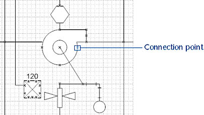
Figure 18-20. Connection points on a shape show where you can connect valves, pipes, and lines.
Labeling HVAC Shapes
HVAC schematics often include a lot of text in the form of shape labels and instructions. In some cases, you can label a shape by selecting it and then typing. Other shapes are locked to prevent this, because they are labeled automatically when configured in certain ways. For example, when you specify a load voltage for a magnetic starter in the Custom Properties window, the voltage is displayed on the shape. To reposition a label, drag its control handle (the yellow diamond).
One cool thing you can do with the HVAC shapes (or any shapes that include custom properties) is to label the shape with a property value automatically, such as the part number or bill of material (B-O-M) tag. To do this, you can insert a text field that displays the custom property (choose Insert, Field), or you can use a custom callout shape.
For details about labels, see "Using Visio Shapes to Display Text."
Adding Ductwork
You can design single-line and double-line HVAC plans that show the location and configuration of ductwork and piping. Visio consolidates the ductwork shapes on one stencil, HVAC Ductwork. (Visio 2000 stored duct shapes on two different stencils depending on whether the ducts were rectangular or circular.) You can configure any duct shape in Visio to be either rectangular or circular in the Custom Properties window.
When you add ductwork to a floor plan, your task is made simpler by some pretty smart shapes. For example, the duct shape is designed to look like a line while you drag it on the page, which makes it easier to position precisely. In addition, control equipment shapes are designed to work together. Dampers, sensors, and other shapes can be dropped on ducts, where they snap and rotate into place. That frees you to concentrate on more important tasks, such as how to design your system for optimum indoor air quality.
To configure ducts, diffusers, and other equipment shapes, right-click a shape, and then choose Properties. The Custom Properties window lists relevant options. For example, to show how a centrifugal fan is used, you can click in the Use field of its Custom Properties window to choose from Supply Air, Return Air, Exhaust Air, and more. To open the Custom Properties window, choose View, Custom Properties Window.
Tip - Drag a Shape to an Exact Position
When you drag a shape such as the Duct shape from the stencil onto the drawing page, watch the status bar at the bottom of the Visio window. The duct's position on the page is given as the x-coordinate and the y-coordinate of the two ends of the duct.
For other shape configuration options, right-click a shape and see whether it has any commands on its shortcut menu. For example, you can specify whether a diffuser (Troffer Outlet shape) is hidden, and you can add fins to or remove the plate from a pipe coil.
HVAC Shapes and Layers
When you add ductwork to an existing floor plan, the shapes are assigned to the HVAC layer, as Figure 18-21 shows. That way, you can lock other drawing layers to prevent them from changing while you add the HVAC equipment, and you can view the floor plan without the HVAC equipment. HVAC shapes can be assigned to more than one layer. For example, you can assign the Starter shape to an HVAC layer as well as the Flow Equipment, Notations, Piping, Power/Comm. and Valve layers. That gives you a lot of flexibility to work with the different information in a floor plan. You can do the following:
- To see which layers a shape is assigned to or add it to a new layer, select the shape, and then choose Format, Layers.
- To work with layers in a drawing, choose View, Layer Properties. For details, see "Using Layers to Protect, Hide, and Organize Shapes."
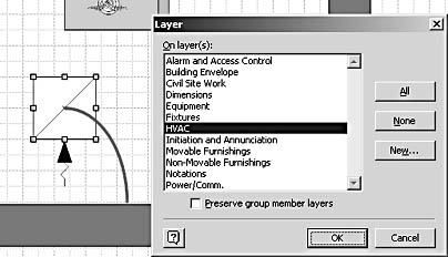
Figure 18-21. Visio duct shapes are preassigned to the HVAC layer, as the Layer dialog box shows.
Drawing the Plumbing Layout
A floor plan can include the layout of pipes, valves, and fittings with shapes from the Plumbing And Piping Plan template. You can also use this template to show drainage in a site plan or to design water supply systems, waste water disposal systems, and other schematics that show water lines, pipes, and valves. When you start a drawing with the Plumbing And Piping Plan template, Visio sets up a scaled drawing page and opens the following stencils:
- Pipes And Valves – Pipes 1 and 2. These two stencils contain shapes that represent a variety of pipelines and devices used with pipelines. The pipelines are 1-D shapes that you can resize and rotate by dragging an endpoint.
- Pipes And Valves – Valves 1 and 2. These two stencils contain standard valve symbols. The blue connection points on valve shapes are designed to be glued to the endpoints on pipeline shapes.
- Plumbing. This stencil includes standard plumbing shapes from the boiler down to the towel bar.
To show plumbing or piping information in an existing floor plan, open the floor plan first, and then open these stencils, which are stored in the Building Plan folder. When you want to start a design from scratch, open the Plumbing And Piping Plan template in the Building Plan folder.
Adding Plumbing Equipment
When you add plumbing equipment and fixtures to a floor plan, you can show a cutaway view of how piping moves through the walls with shapes that represent a side perspective. Or you can show the customary top-down view of fixtures in a floor plan. Some shapes also include shortcut commands that you can use to change their appearance. For example, a boiler can be displayed with flat, curved, or angled ends, as Figure 18-22 shows. To determine whether a shape has shortcut commands, right-click the shape.
Other shapes include custom properties that affect how they're displayed, although none of the shapes on the Plumbing stencil do this. So even if you don't see a particular symbol on a stencil, Visio might include a configurable shape that looks the way you want. For example, you can change the In-Line Valve shape on the Pipes And Valves – Valves 1 stencil to be displayed as an in-line, 3-way, or 4-way valve, as Figure 18-23 shows. To find out whether a shape can be customized, display its Custom Properties window or right-click the shape, and then select Properties to display its Custom Properties dialog box.
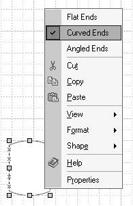
Figure 18-22. Right-click a shape to see its shortcut menu with commands for configuring the shape's appearance.
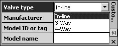
Figure 18-23. You can change the configuration for some shapes in the Custom Properties window. Each of the piping, valve, and plumbing shapes includes at least three custom properties: Manufacturer, Model ID, and Model Name.
InsideOut
When you use the drawing tools to create fixtures such as a T-joint, you might need to rotate them, but only 90-degree orientations are valid. If you're drawing pipes or other representational lines with the Line tool, you can snap lines to specific angles with shape extension lines. To turn on shape extension lines, choose Tools, Snap & Glue. On the General tab, select Drawing Aids. On the Advanced tab, scroll down the list, and then select Isometric Angle Lines. In the Isometric Angles box, type the angle measure (in degrees) of the angle you want the line to snap to.
The isometric angle lines were originally developed for diagrams where pipes run horizontally and vertically. When it doesn't make sense to rotate shapes at other angles, you can use shape extension lines to show you how to constrain lines to a valid angle when you draw them.
Using Layers with Piping Shapes
All the plumbing, piping, and valve shapes are assigned to layers, which gives you added flexibility when adding shapes to an existing floor plan. For example, the Power Signal shape is assigned to both the Valve layer and the Flow Controller layer. The Heating/Cooling Coil shape is assigned to the Plumbing and the Flow Equipment layers. You can work with shapes selectively based on their layer assignments.
For details about working with layers, see "Using Layers to Protect, Hide, and Organize Shapes."
Tip
To keep pipes together after you've laid them out on the drawing page, you can group them: select the shapes you want, and then press Shift+Ctrl+G.
You can use any of the plumbing, piping, and valve shapes to track information about manufacturer, model or tag number, and model name. These attributes are included as custom property fields that you can fill out and then use to generate reports, parts lists, or bills of material using the Tools, Report command. To see the properties associated with a shape, display the Custom Properties window (choose View, Custom Properties Window).
Adding Electrical and Telecommunication Services
The Electrical And Telecom stencil provides the shapes you need to show the location of lighting, outlets, service panels, and so on in a home, office, or manufacturing plant, as Figure 18-24 shows. When you're working in a floor plan, you can open this stencil by clicking the drop-down arrow on the Open Stencil button on the Standard toolbar, and then selecting Building Plan, Electrical And Telecom.
You can use the Electrical And Telecom Plan template to create a diagram from scratch. This template opens the Electrical And Telecom stencil as well as the Drawing Tools and Walls, Shell And Structure stencils. To start a new electrical plan, choose File, New, Building Plan, Electrical And Telecom Plan.
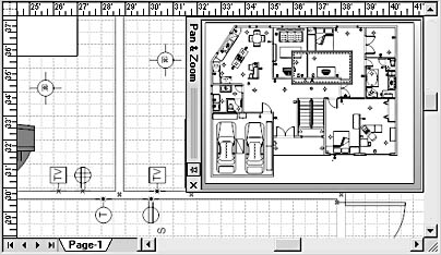
Figure 18-24. This floor plan shows the placement of switches, outlets, smoke detectors, ceiling lights, and doorbell chimes with shapes from the Electrical And Telecom stencil.
Configuring Electrical and Telecommunication Shapes
There are more symbols that you can display than there are shapes—several shapes include custom properties that you can set to show different types of outlets, switches, and so forth. For example, the Switches shape can represent single pole, 3-way, 4-way, timer, or weatherproof switches. The Socket Outlets shape can represent standard, dedicated, or split-wire outlets. To find out whether a shape has configurable properties, right-click a shape, and then select Properties to display the Custom Properties dialog box for that shape.
To configure a shape, right-click the shape to display a shortcut menu with options. For example, you can right-click a service panel and specify whether to display it as an inset or surface panel.
Some of the lighting shapes provide built-in options. For example, you can specify the fitting size of the Surface Floures shape in the Custom Properties window. With the Troffer Floures shape, you can choose the number of lamps (1 to 4) as well as the length (4 feet or 8 feet).
InsideOut
If you used the electrical and telecommunication shapes in Visio 2000, you'll notice that Visio 2002 doesn't prompt you for information when you drag a shape from the stencil onto the drawing page. This change represents a philosophical shift among the product designers—they now think such prompts are intrusive.
Connecting and Positioning Electrical Shapes
Outlets and switches are designed to connect to wall shapes in a floor plan, but they aren't smart enough to rotate themselves into position. If the shape is oriented differently than the wall you want to attach it to, you can rotate it manually with the Rotation tool on the Standard toolbar. If you want to reverse the shape's orientation, there's a shortcut: right-click the outlet or switch, and then choose Flip Orientation.
Tip
To quickly rotate a shape 90 degrees to the left, press Ctrl+L. To rotate a shape 90 degrees to the right, press Ctrl+R.
If you want to show connection wires between the switches in a floor plan, you'll need to draw them; Visio doesn't have an automated method. Use the Freeform tool on the Standard toolbar. Freeform lines are a little tricky to draw—it's best to drag very slowly when using this tool. To connect lines, click the Freeform tool, and then drag from a connection point on the shape where the connection wire starts to the connection point on the shape where the wire ends.
Tip
For more electrical and electronic symbols, see the templates and stencils in the Electrical Engineering folder. For shapes that represent telecommunication devices (such as cell phones and pagers), see the Telecom stencil in the Network folder.
Adding Security Systems
You can add video surveillance and other cool security devices to your floor plans with shapes from the Security And Access Plan template. Visio includes shapes for surveillance cameras, intercom systems, alarms, and other devices, as Figure 18-25 shows. You can start a security and access plan on a blank page or as a layer in an existing floor plan. To design a security system from scratch, you can open the Security And Access Plan template, which opens a scaled drawing page and the following stencils:
- Alarm And Access Control. This stencil includes shapes for various card readers, keypads, and other access devices.
- Initiation And Annunciation. This stencil contains shapes for designing digital- and microprocessor-controlled intercom paging and alarm systems.
- Video Surveillance. This stencil includes shapes for motion detectors, sensors, cameras, and switches.
Figure 18-25. This partial floor plan shows a camera (C), ceiling-mounted microwave motion detector (CM), wall-mounted smart card–type card reader (WS), ceiling-mounted burglar alarm (CB), and hidden panic button (HP) shapes.
Adding Security System Shapes
To add security systems to an existing floor plan, you can start in one of two ways:
- To insert security systems in a floor plan you created in Visio, open the floor plan, and then use the Open Stencil button on the Standard toolbar to open the stencils you need in the Building Plan folder.
- To add security systems to a floor plan created in a CAD program, start in Visio by selecting File, New, Building Plan, Security And Access Plan. Then insert the CAD drawing (Insert, CAD Drawing). For details, see "Using a Floor Plan from a CAD Drawing", or refer to Chapter 17, "Using CAD Drawings in Visio."
Configuring Security System Shapes
You can configure some security devices by setting properties in the Custom Properties window. For example, you can specify how a device is mounted—on the ceiling, rack, desk, wall, and so on—by choosing an option, as Figure 18-26 shows. The shape's label changes to reflect the type of mount. To view a shape's custom properties, open the Custom Properties window or right-click the shape, choose Properties, and make the changes in the Custom Properties dialog box.
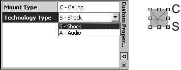
Figure 18-26. To see the configurable properties for security and alarm shapes, anchor the Custom Properties window on the drawing page. This Glass Break Sensor shape includes options for the type of mount and technology (audio or shock).
Security and alarm shapes are assigned to layers. When you add these shapes to a floor plan, Visio adds the Security, Surveillance, and Video Surveillance layers to the drawing depending on the shapes used. You can take advantage of layers to selectively show and print shapes in a drawing.
For details about working with layers, see "Using Layers to Protect, Hide, and Organize Shapes."
EAN: 2147483647
Pages: 211