DWDM
| As a means of introduction, next you will look at a brief history of DWDM and how DWDM is delivered from MSPPs. History of DWDMIn the mid-1980s, the U.S. government deregulated telephone service, allowing small telephone companies to compete with the giant AT&T. Companies such as MCI and Sprint quickly went to work installing regional fiber-optic telecommunications networks throughout the world. Taking advantage of railroad lines, gas pipes, and other rights of way, these companies laid miles of fiber-optic cable, allowing the deployment of these networks to continue throughout the 1980s. However, this created the need to expand fiber's transmission capabilities. In 1990, Bell Labs transmitted a 2.5-Gbps signal over 7500 km without regeneration. The system used a soliton laser and an erbium-doped fiber amplifier (EDFA) that allowed the light wave to maintain its shape and density. In 1998, they went one step further as researchers transmitted 100 simultaneous optical signals, each at a data rate of 10 Gbps, for a distance of nearly 250 miles. In this experiment, DWDM (technology that allows multiple wavelengths to be combined into one optical signal) increased the total data rate on one fiber to 1 terabit per second (Tbps, or 1012 bits per second). Today DWDM technology continues to develop. As the demand for data bandwidth increases (driven by the phenomenal growth of the Internet and other LAN-based applications such as storage, voice, and video), the move to optical networking is the focus of new technologies. At the time of this writing, more than one billion people have Internet access and use it regularly. More than 50 million households are "wired." The World Wide Web already hosts billions of web pages, and, according to estimates, people upload more than 3.5 million new web pages every day. The important factor in these developments is the increase in a fiber's capacity to transmit data, which has grown by a factor of 200 in the last decade. Because of fiber-optic technology's immense potential bandwidth (50 terahertz [THz] or greater), there are extraordinary possibilities for future fiber-optic applications. Alas, as of this writing, carriers are planning and launching broadband services, including data, audio, and especially video, into the home. DWDM technology multiplies the total bandwidth of a single fiber by carrying separate signals on different wavelengths of light. DWDM has been a core technology in long-haul core networks, where it has been used successfully for many years to vastly increase the capacity of long-haul fibers. Metro networks are now realizing the same benefit: With DWDM, a fiber that now carries a single OC-48 can carry a dozen or more equivalent colors of light. This transforms what was a single-lane road to a multilane freeway. One distinction to note is that metro DWDM must be designed differently than long-haul DWDM. In long-haul applications, DWDM systems must handle the attenuation and signal loss that are resident in connections over hundreds of miles. In metro applications, however, where distances are measured in tens of miles, attenuation is not the primary challenge. Unlike point-to-point long-haul connections, metro rings have many add and drop access points to the network. Therefore, metro DWDM systems must be designed to provide the flexibility for adding and dropping individual wavelengths at different access points in the network, while passing along the wavelengths that are not needed at those points. As you already know, DWDM is an MSPP service that does not ride within a SONET frame. On the contrary, as Figure 3-15 and Figure 3-16 show, the SONET frames can be carried within the wavelength. Figure 3-15. Metro DWDM Bandwidth Management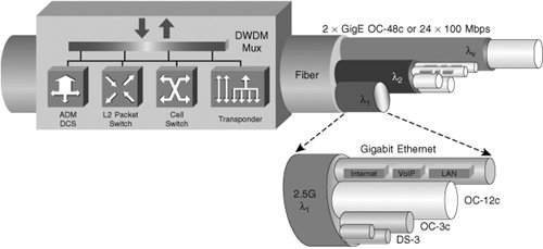 Figure 3-16. Metro DWDM as Enabler Adding wavelengths (or lambdas, as they are often called, after the Greek letter that is the physical symbol for wavelength) enlarges the pipe, but it is important to use the extra capacity efficiently as well. Next-generation metro transport platforms provide the versatility needed to groom smaller services efficiently onto each wavelength. As you have seen already, next-generation platforms can handle traditional DS1 and DS3 services, 10-/100-Mbps, GigE services, and interfaces to TDM transport that scale from DS1 (1.5 Mbps) to OC-192 (10 Gbps). Used in combination with metro DWDM technology integrated into the platform, these systems give carriers the capability of scaling their service offerings, including these:
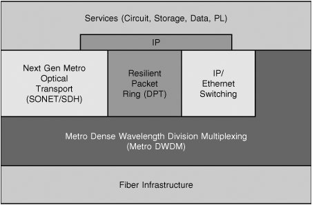
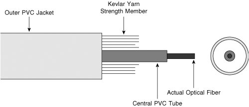
Figure 3-15 shows the aggregation of these various types of services on a DWDM fiber. Figure 3-16 shows the varied layering of transport and service protocols that is possible over DWDM wavelengths. By enabling such a wide range of service offerings, DWDM plus next-generation metro transport addresses the overriding concerns of service density and service velocity: the amount of time it takes to deploy a service to a customer. Greater capacity and efficiency enable carriers to approach the maximum service densitythat is, the greatest total number of services that can be provided on each wavelength of the fiber. High service density means that the greatest number of customers are served by a given capital investment in network infrastructure. At the same time, carriers can achieve higher service velocity in a competitive marketplace. With maximum bandwidth available and flexible bandwidth management, carriers can introduce new services and modify existing ones more quickly, and then make service alternatives available faster to a wider range of customers. Fiber-Optic CableFiber-optic cable comes in various sizes and shapes. As with coaxial cable, its actual construction is a function of its intended application. It also has a similar "feel" and appearance. Figure 3-17 is a sketch of a typical fiber-optic cable. Figure 3-17. Fiber-Optic Cable Construction The basic optical fiber is provided with a buffer coating, which is mainly used for protection during the manufacturing process. This fiber is then enclosed in a central PVC loose tube, which allows the fiber to flex and bend, particularly when going around corners or when being pulled through conduits. Around the loose tube is a braided Kevlar yarn strength member, which absorbs most of the strain put on the fiber during installation. Acceptance of Light onto FiberLight is directed into a fiber in two ways. One is by pigtailing; the other is by placing the fiber's tip close to a light emitting diode (LED). When the proximity type of coupling is employed, the amount of light that will enter the fiber is a function of one of four factors:
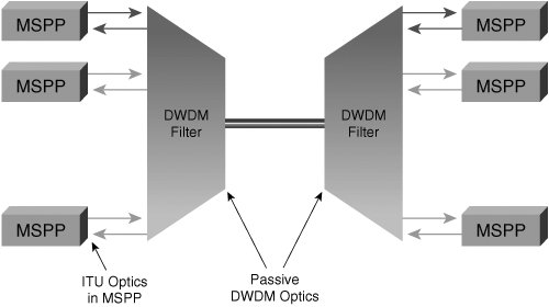
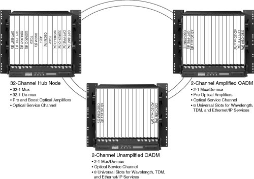
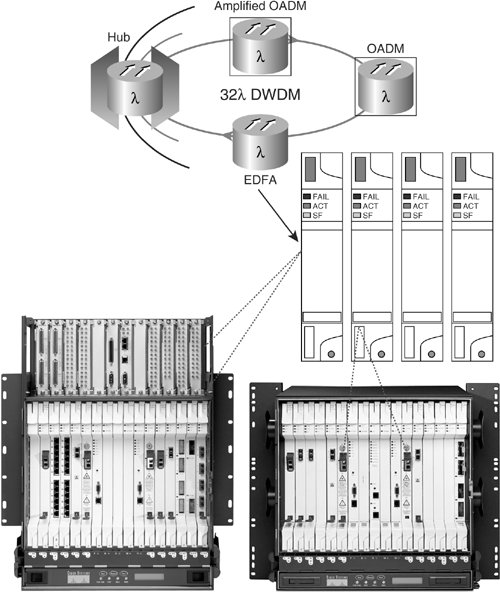
Wavelength-Division Multiplexing: Course Wavelength-Division Multiplexing versus DWDMBefore we go any further, let's distinguish among wavelength-division multiplexing (WDM), course wavelength-division multiplexing, and DWDM, even though the focus remains on DWDM. WDM technology was developed to get more capacity from the existing fiber-optic cable plant by using channels (wavelengths) to carry multiple signals on a single fiber. Two major categories of WDM are used: CWDM and DWDM. A major difference between the two, as their names imply, is the channel spacing within the window of the optical spectrum. The wide pass-band (20 ± 67 nm) of CWDM channels allows for the use of less expensive components, such as uncooled lasers and thin-film filter technology. CWDM systems provide cost advantages over DWDM in the same application. As such, many people push CWDM as a more appropriate platform for the shorter distances typically found in metro access networks. Sometimes metro networks require longer distances and more wavelengths than CWDM can provide, however. Today CWDM does not practically support more than the 18 channels between 1271 and 1611 nm, standardized by the ITU Telecommunication Standardization Sector (ITU-T) G.694.2 wavelength grid. Relatively low-cost "metro" DWDM can pack many 2.5- and 10-Gbps wavelengths (up to 40), onto a single fiber. However, to do so, precision filters, cooled lasers, and more space are needed, which can make DWDM too expensive for some edge networks. What is the best solution for a given application? Depending on cost, distance, and the number of channels, metro-area networks might benefit from a mixture of both coarse and dense WDM technologies. Early WDM deployments emerged in the form of "doublers," which used 1310-nm and 1550-nm lasers through passive filters to transport two signals on a single fiber. This simple approach was reliable, low in cost, and easy to operate, which made it suitable for carrier networks. Other WDM techniques were customized for specific applications. CWDM was used mostly in LANs because of the reach limitations imposed by operating in the 850-nm range. By the early 1990s, WDM development was focused on solving capacity shortages experienced by interexchange carriers. Their national backbone networks presented a different set of parameters and cost structure. This enabled the use of more complex and expensive components, which made high-capacity transport over long distances possible. With its narrow channel spacing (1.6 and 0.8 nm), DWDM allowed many wavelengths in a small window of optical spectrum. Narrow channel spacing is important for long distances because fiber attenuation is lowest in the C-band. DWDM Integrated in MSPPTraditionally, SONET platforms have been dedicated to services that could be encapsulated within SONET frames. Today vendors not only can deliver SONET services from MSPPs, but they also can hand off these services in a DWDM wavelength service. Figure 3-18 shows a DWDM networked environment that uses the MSPP architecture. Five aspects will be discussed with regard to integrating DWDM into MSPPs; active vs. passive DWDM, EDFAs, DWDM benefits, protection options, and market drivers for MSPP-based DWDM. Figure 3-18. Metro DWDM Integrated within the MSPP Architecture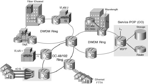 Active and Passive DWDMDWDM can be implemented with an MSPP in two ways. Most often when you think about DWDM systems, you probably think of active DWDM systems. However, the multiplexing of multiple light sources is always a "passive" activity. Wavelength conversion and amplification is always the "active" DWDM activity. Figure 3-19 shows an MSPP chassis with integrated DWDM optics in which the optics cards (in this case, OC-48s) use one of the ITU wavelengths and interfaces to an external filter. This filter multiplexes the wavelengths from various optics cards within multiple chasses and transports them over the fiber, where they are demultiplexed on the other end. This is known as passive DWDM with respect to the MSPP because the filter is a separate device. Figure 3-19. MSPP Chassis with Integrated ITU Optics Card Connected to East and West DWDM Filters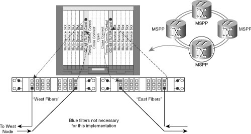 This inefficient use of the rack and shelf space has led to the development of active DWDM from the MSPP. With active DWDM, the transponding of the ITU wavelength to a standard 1550-nm wavelength is performed by converting the MSPP shelf into various components required in a DWDM system. This conversion has greatly increased the density of wavelengths within a given footprint. Under the passive example shown in Figure 3-20, only 16 wavelengths could be configured within a bay, 4 per chassis. With today's multiport, multirate optical cards, this density can be doubled to 8 wavelengths per shelf and 32 per rack. Figure 3-20. MSPP with Integrated ITU DWDM Optics Connected to Filters That Multiplex the Wavelengths With the integrated active DWDM solution of Figure 3-20, one MSPP chassis can be converted into a 32-channel multiplexer/demultiplexer using reconfigurable optical add/drop multiplexing (ROADM) technology. Other chassis can be converted into a multichannel optical add/drop multiplexer (OADM), which can receive and distribute multiple wavelengths per shelf. The implication of this is that up to 32 wavelengths can be terminated within a bay or rack, a factor of eight times the density of even early MSPPs using a passive external filter. The traffic from within each wavelength dropped into an MSPP shelf from the ROADM hub shelf can be groomed or extracted from the wavelengths carrying it, as needed, and dropped out of the OADM shelves, as shown in Figure 3-21. ROADM is an option that can be deployed in place of fixed-wavelength OADMs. Cisco Systems ROADM technology, for example, consists of two modules:
It uses two sets of these modules for East and West connectivity, allowing for 32-channel add/drop/pass-through support with no hardware changes. At each node, software controls which wavelengths are added, dropped, or passed through, on a per-wavelength basis. Erbium-Doped Fiber AmplifiersErbium-doped fiber amplifiers (EDFAs) can be integrated within the DWDM MSPP shelf as well as optical service channel cards for management. These amplifiers extend the distance of the signal by amplifying it. Features of EDFAs include these:
The adjustable gain of the EDFAs can be used to reset a network to a better operating point after a change in span loss. DWDM AdvantagesMany benefits are tied to having a DWDM over MSPP, including scalability, rapid service velocity, and flexibility (to name a few). Some of these benefits are shown as follows:
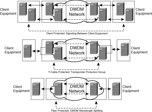
Note With so many advantages, one of the disadvantages is that paradigm shift is required to move the market toward MSPP-based DWDM. This slow migration is keeping vendors at bay in terms of development as they try to balance investment in the future with today's revenue. Figure 3-22 shows an active transponder-based DWDM. Figure 3-22. Active Transponder-Based DWDM with EDFAs Integrated into the Shelf Protection OptionsSeveral ways exist for protecting an MSPP-based DWDM system in the event of a fiber cut or signal degradation. Such protection options include client protection, Y-cable protection, and wavelength splitting. Figure 3-23 shows these protection types. They are described as follows:
Reliability for these options varies, depending on the client network architectures and service-level agreements (SLA) provided to the client. Thus, there is no "one size fits all" approach to protection. Market Drivers for MSPP-Based DWDMOne of the main obstacles to the adoption of DWDM technology in metro networks is the inflexibility associated with first-cost and network growth. The MSPP-based DWDM has been architected for networking flexibility and growth:
|
EAN: 2147483647
Pages: 140