Section 8.2. Flooding Enhancements
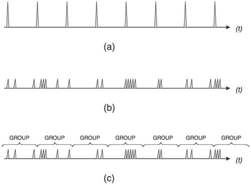
8.2. Flooding EnhancementsSection 8.1.5 refers several times to network instabilities causing a flood of LSA/LSPs, but the focus is on enhancing SPF so that the router's processor is not overwhelmed during unusually busy periods. In other words, the focus is on the router protecting itself. But as in any community, self-protection becomes less of an issue if all the members of the community behave themselves and watch out for their neighbors. In the case of link state protocols, enhancing the flooding mechanism to reduce the chance that a router will overwhelm a neighbor or an area with LSA/LSPs makes a router a better neighbor. As with SPF enhancements, most flooding enhancements are not a part of the open protocol specifications. (IS-IS mesh groups are the exception.) They have been developed by vendors in an effort to make their OSPF and IS-IS implementations scalable to large networks. What enhancements are developed by a given vendor likely depend on the specific kinds of networks the vendor's routers must accommodate and the features requested by the vendor's customers. 8.2.1. Transmit PacingIncreasing the interval between subsequent LSA/LSP transmissions is variously called delay, pacing, or throttling. Whatever you want to call it, delaying the transmission of LSA/LSPs prevents a router from dominating a link or overwhelming a neighbor. There are two aspects to delaying LSA/LSP transmission: delaying self-originated LSA/LSPs, and delaying LSA/LSPs forwarded through the router during the flooding process. To understand how delaying can help make flooding more efficient, consider first a naïve implementation that refreshes at some set interval (every 30 minutes for OSPF, every 20 minutes for IS-IS). Whenever the refresh timer expires, the link state database is scanned and all of its self-originated LSAs or LSPs are flooded. This single-timer refresh interval results in a periodic, heavy flooding interspersed by equal periods of complete quiet, as illustrated in Figure 8.30(a). Implementing individual refresh timers for each LSA/LSP spreads the refresh load out randomly, as shown in Figure 8.30(b), so that neighbors are not hit with a large number of LSA/LSPs all at once. Figure 8.30. A single refresh timer for the entire link state database results in possibly heavy floods every refresh interval (a), whereas separate refresh timers for each database entity results in smaller, more random floods (b). Adding a delay to the individual refresh timers improves efficiency by grouping several entities into one flood (c). However, individualizing the refresh timers is not as efficient as it could be, especially for OSPF where Update packets might carry a single or a very few LSAs. If, instead of immediately transmitting an LSA when its refresh timer expires, the transmission is delayed for some period, additional refresh timers are more likely to expire during the waiting period and more LSAs can be carried in a single Update. The "grouping" effect of this delay is shown in Figure 8.30(c). Cisco's IOS uses a default LSA pacing timer of 4 minutes; the timer can be changed to between 10 seconds and 1800 seconds (30 minutes) with the command timers pacing lsa-group[5] This pacing applies not only to LSA refreshing but also to aging and checksumming. If the link state database is very large, on the order of thousands of LSAs, the default pacing delay might cause spikes in the flooding similar to those in Figure 8.30(a); reducing the pacing delay can smooth out the flooding pattern.
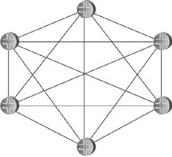
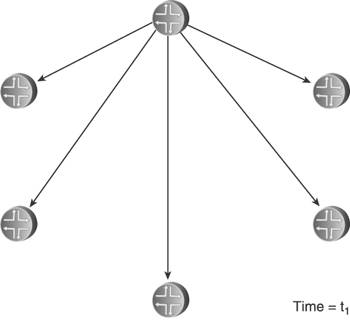
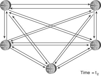
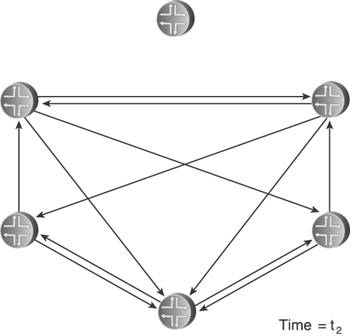
Delaying the transmission of self-originated LSA/LSPs has its greatest benefit when there is instability local to the routermost usually the flapping of a connected link. Rather than flooding a new LSA/LSP every time the link changes state, a delay period might span several state changes, thereby dampening the impact the flapping has on flooding activity. Both OSPF and IS-IS standards do specify delays that help in this regard. OSPF specifies two architectural constants: New instances of a given LSA cannot be generated more frequently than 5 seconds (MinLSInterval), and new instances of a given LSA cannot be received more frequently than 1 second (MinLSArrival). IS-IS specifies similar delays, although ISO 10589 suggests values for the delays rather than making them constants: 30 seconds between the generation of new LSPs (minimumLSPGenerationInterval), and 5 seconds between transmissions of LSPs from the same originator (minimumLSPTransmissionInterval). Vendor implementations often enhance these basic delays to scale to different network sizes. Cisco's IOS uses the same exponential backoff mechanism described in Section 8.1.5 to throttle the transmission of self-originated LSPs: Using the command lsp-gen-interval, you can specify initial delay, delay increment, and maximum delay periods. As described, the initial delay specifies the time to wait, in milliseconds, after the first generation of a new LSP before transmitting it. The delay increment is the multiplier used to exponentially increase the delay between subsequent transmissions, in milliseconds. The interval between the first and second transmission is the delay increment value, and then the interval between subsequent transmissions is twice the interval of the previous transmission: IncrementValue, 2*IncrementValue, 4*IncrementValue, 8*IncrementValue, and so on, until the maximum delay value, specified in seconds, is reached. The delay between subsequent transmissions then remains at the maximum delay. If no new LSPs are generated for twice the maximum delay value, at that point the exponential backoff mechanism is reset. Juniper's JUNOS does not use an exponential backoff, nor does it provide configurable options for the LSP delay. Instead, it uses a "fast mode" and "slow mode" scheme similar to that described for its SPF delay in Section 8.1.5. The normal "fast mode" transmission delay of self-originated LSPs is 20ms. If three LSPs are generated in quick succession, IS-IS switches to "slow mode" and delays each transmission by 10 seconds until the network stabilizes. The other aspect of transmission pacing is the control of flooding of LSA/LSPs originated by other routers. In times of instability, hundreds or thousands of LSA/LSPs can be flooded within an area; a router must be able to pace the transmission of OSPF Updates or IS-IS LSPs to limit the rate its neighbors receive these messages. IOS uses the command timers pacing flood to configure the minimum interval, in milliseconds, between transmitted OSPF Update packets. The default interval is 33ms and can be changed in the range of 5 to 100ms. JUNOS uses a hard-coded delay interval that cannot be changed. For IS-IS, IOS uses the command isis lsp-interval to specify the pacing of LSP transmissions. The default is again 33ms. JUNOS uses the very similar command, lsp-interval, to change its default interval of 100ms. Simple arithmetic shows that an interval of 100ms, for example, means that Updates or LSPs cannot be transmitted any faster than one every .1 seconds, or a maximum transmission rate of 10 packets per second; 50ms means a maximum rate of 20 packets per second, and so on. In all cases, these commands are configured per interface so that the change from the default is applied to specific neighbors. It must be noted that in the great majority of cases, the default (or hard-coded) transmission interval is sufficient. There are better ways to protect a low-powered neighbor from the impact of large-scale flooding, such as good OSPF area design and well-designed packet queues. 8.2.2. Retransmit PacingYet another aspect of controlling flooding is the pacing of LSA/LSP retransmits. Recall from the discussion in Chapter 5 that flooding must be reliable, and so LSA/LSPs that are not acknowledged either implicitly or explicitly within a specified time are retransmitted. OSPF does this by placing a copy of a transmitted LSA on a Retransmit List and setting a retransmit timer (normally 5 seconds). If the LSA is acknowledged, it is removed from the Retransmit List. If the retransmit timer expires, a copy of the LSA is retransmitted and the retransmit timer is restarted. The IS-IS retransmission process for point-to-point and broadcast links is different. On point-to-point links, the Send Routing Message (SRM) flag of a transmitted LSP is not cleared until the LSP is explicitly acknowledged with a PSNP. So if the SRM for that link is still set the next time the LS database is scanned (which happens every 5 seconds or minimumLSP-TransmissionInterval), the LSP is retransmitted. On broadcast links, transmitted LSPs are always implicitly acknowledged by CSNPs, transmitted by the DIS every 10 seconds. If a router does not see the instance of an LSP that it transmitted in the next received CSNP, it retransmits the LSP. The problem here is that if flooding is heavy, a low-powered router might be so busy processing received LSA/LSPs that it does not acknowledge their receipt promptly, causing its neighbors to retransmit. If the router is already busy, the retransmissions can just make matters worse. You can use the IOS command ip ospf retransmit-interval or the JUNOS command retransmit-interval to change the default OSPF retransmission interval from 5 seconds to an interval in the range of 1 to 65,535 seconds; both commands are applied per interface. IOS can also change the default IS-IS retransmission interval of 5 seconds on point-to-point links using the command isis retransmit-interval. The interval you can set with this command ranges from 0 to 65,535 seconds. Although this command changes the interval between scans of the database for any SRM flags set for the interface, there is another commandisis retransmit-throttle-intervalthat actually controls the rate, in milliseconds, at which retransmitted LSPs are sent. JUNOS does not allow the default IS-IS retransmission interval to be changed. 8.2.3. Mesh GroupsFlooding load is a particular problem in heavily meshed networkssuch as those built on ATM or Frame Relay infrastructures. Recall from the basics of flooding that when a router receives a flooded LSA/LSP, it forwards it to all neighbors except the one from which it received the data unit. This is simple split-horizon forwarding. With heavily meshed networks, however, each router has many paths to other routers; in a fully meshed network such as the one in Figure 8.31, each router has a connection to every other router. This meshing means that there are numerous ways for an LSA/LSP to be replicated so that one router is likely to receive many copies of the same LSA/LSP. In Figure 8.32, for example, a router originates and floods an LSA or LSP. The direct connections mean that the information is communicated to all other routers with this initial flood. But the other routers have no way of knowing that all of their neighbors have received the information, so they flood the LSA/LSPs to all neighbors except the one they received the information from as shown in Figure 8.33. This second phase of flooding is entirely unnecessary. Figure 8.31. In a fully meshed network, every router has a connection to every other router. Figure 8.32. When a router floods an LSA or LSP in a fully meshed network, the information is immediately received by all other routers. Figure 8.33. Because the other routers in the meshed network have no way to know that their neighbors have received the flooded information, they unnecessarily flood to their neighbors. In a fully meshed network, every router except the originator will flood (n 2) unnecessary LSA/LSPs, where n is the number of routers in the network. This works out to (n 1)(n 2) or (n2 3n + 2) unnecessary LSA/LSPs. The example network shown here is small enough that the extra flooding load20 extra LSA/LSPsdoes not significantly impact network resources. As the network grows larger, however, the waste of resources also becomes larger. One flooded LSA/LSP in a fully meshed network of 50 routers, for example, results in 2352 unnecessary replications; in a network of 100 routers, 9702 unnecessary LSA/LSPs are flooded. IS-IS provides a technique for limiting the scope of unnecessary flooding called mesh groups.[6] Mesh groups apply to point-to-point interfaces, and when mesh groups is enabled an interface can be in one of three modes:
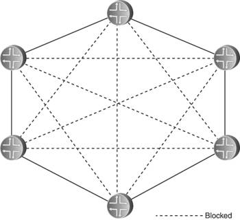
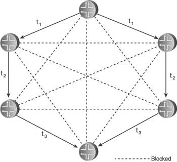
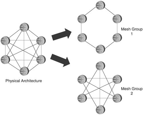
Inactive mode means the mesh group is inactive for that interface, and LSPs are flooded normally. In blocked mode, no LSPs are flooded out that interface. Figure 8.34 shows how blocked mode might be applied to the network in Figure 8.31. Here, all links depicted with a dashed line are in blocked mode and do not flood LSPs. Each router has two unblocked links, so flooding can still take place if any one link fails. However, some redundancy is exchanged for scalability. If both of the unblocked links to one of the routers fail, the router cannot flood LSPs even though it still has three perfectly goodbut blockedlinks to the rest of the network. Figure 8.34. Interfaces in blocked mode do not flood any LSPs. Some convergence time might also be sacrificed. In Figure 8.35, for example, an LSP flooded from one router must pass through a few other routers before the LSP reaches all routers, even though the originator has direct links to every router. Figure 8.35. Blocking LSP flooding on some interfaces can slightly increase overall network convergence time. Set mode offers a compromise between the sharply reduced flooding load but reduced redundancy and increased convergence time of blocked mode. Rather than grouping all interfaces into either blocked or unblocked, set mode groups interfaces into numbered groups. For example, in Figure 8.36 all interfaces belong to either group 1 or group 2. The rule for set mode is then very simple: A received LSP is not flooded out any interface belonging to the same group as the interface on which it was received. Figure 8.36. Set mode assigns interfaces to a numbered group. Suppose a router in the network of Figure 8.36 originates an LSP, as shown in Figure 8.37. As the originator, it floods the LSP to all neighbors. Comparing this illustration with the numbered mesh groups in Figure 8.36, you can see that some neighbors receive the LSP on an interface belonging to mesh group 1 and some neighbors receive the LSP on interfaces belonging to mesh group 2. Figure 8.37. When an LSP is initially flooded, it is received by some neighbors on group 1 interfaces and by some neighbors on group 2 interfaces.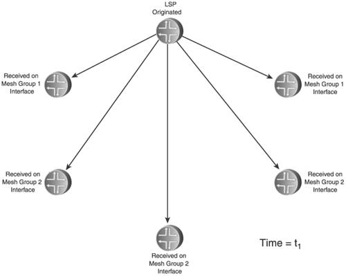 In Figure 8.38, the neighbors flood the LSP. Comparing the illustration to the groups in Figure 8.36, you can see that if the LSP was received on a group 1 interface, it is not flooded on any group 1 interface; and if the LSP was received on a group 2 interface, it is not flooded on any group 2 interface. You can also see that although there is less unnecessary flooding than in the fully meshed network in Figure 8.33, there is more than with the blocked mode in Figure 8.35. However, the reduced convergence seen with the blocked mode architecture is eliminated in this set mode architecture. Figure 8.38. Neighbors flood the received LSP only on interfaces belonging to groups other than the receiving interface's group. In more complex topologies than shown here, you can use a combination of inactive, blocked, and set mode interfaces to manage the flooding patterns in the network. However, any time you use mesh groups, you trade some redundancy or convergence time or both for improved scalability, so you should consider carefully whether mesh groups are right for your network and, if so, design them carefully for the best balance between reduced flooding and reduced reliability. OSPF does not have a comparable feature to IS-IS mesh groups. But some implementations do provide an LSA filtering function that enables you to create an effect similar to mesh groups. The Cisco IOS database-filter command, for instance, can be applied to block the flooding of LSAs on a given interface. However, OSPF networks typically consist of multiple areas that help scale flooding, whereas IS-IS is often used in very large, single-area networks where flooding load is more of a problem. Therefore, mesh groups are not as important for OSPF as they can be for IS-IS. 8.2.4. Demand Circuits and Flood ReductionAlthough IS-IS is usually found only in relatively large IP networks, OSPF is found in networks of all sizes. And in small networks, you are more likely to find demand circuitslinks that should be used only when there is a demand for them, and should otherwise be silent. The most common modern examples of demand circuits are links that treat data exchanges as a "call," such as dial-up and low-bandwidth ISDN. You do not want such connections to stay up permanently. Demand circuits also include any circuit for which you are billed based on the amount of packets traversing it. Running OSPF over demand circuits is problematic because the Hellos will either keep the circuit up permanently or cause the circuit to connect and disconnect every 10 seconds just to transport the Hello packets. Additionally, periodically refreshing LSAs across a demand circuit when nothing has changed can cause unwanted connections or billing. An extension to OSPF makes the following modifications to accommodate demand circuits:[7]
If an LSA is not going to be periodically refreshed across a demand circuit, it must not "age out" of the link state databases in which it resides. That is, the age should not reach MaxAge. To accomplish this, the highest-order bit in the 16-bit Age field of the LSA header is designated as the DoNotAge bit. When this bit is set in an LSA, the age is incremented as usual during flooding, but is not incremented after the LSA has been installed in the link state database. Of course, for this scheme to work all routers must understand and support the DoNotAge bit. If one router in the area does not, and increments the age to MaxAge, it will delete the LSA and the databases in the area will no longer be identical. Therefore, for OSPF over demand circuits to be reliable, all routers in an area must indicate their support for the extension by setting the Demand Circuit (DC) bit in the Options field of all LSAs it originates (Figure 8.39). If any LSA appears in any link state database in the area with the DC bit cleared, the router flushes all DoNotAge LSAs from its database.[8] The originators of these LSAs must then flood new instances, with the DoNotAge bit cleared. The DC bit is also set in the Options field of Hello and Database Description packets sent across demand circuits during synchronization, to negotiate an agreement to stop sending Hellos after the neighbors are synchronized.
Figure 8.39. The DC bit in the Options field indicates support for DoNotAge LSAs. Because all LSAs in an area in which OSPF is running over a demand circuit must have their DC bits set, it is best to put demand circuits in stub, totally stubby, or NSSA areas. Doing so eliminates the necessity of an ABR or ASBR having to set the DC bits in all type 3, 4, and 5 LSAs. Obviously, if LSAs are not being refreshed periodically, some of the robustness inherent to OSPF is lost. This should be a factor when considering whether to run OSPF over a demand circuit. Another consideration is that with no Hellos exchanged across a demand circuit, there is no keepalive function. If a router on one end of the circuit becomes unreachable, the neighbor on the other end will not detect it. A solution to the detection of a failed neighbor, called neighbor probing, is proposed in RFC 3883.[9] With neighbor probing, any time the link is connected for the transmission of application packets OSPF can send Updates and look for Acknowledgments. However, probing only takes place when the link is up for packet transmission; the link is not brought up just for probing.
There is also a potential situation in which the neighbor is available but the link is not. Again, the lack of Hellos means this condition cannot be detected. So, there must be a presumption of reachability, meaning that the circuit is presumed to be available when needed. If for some reason a connection cannot be established, OSPF does not report the link as down. Instead, the link is considered oversubscribed and packets destined to transit the link are dropped. Yet another consideration has to do with network management software. The routers at each end of a demand circuit still refresh their LSAs out all other interfaces; periodic refreshes are suppressed only across the demand circuit. This means that the sequence number of the same LSA might not match in databases on each side of the circuit, which can lead some network management applications to falsely conclude that the databases in an area are not synchronized. All in all, running OSPF over demand circuits in a modern network is probably a bad idea. The extension was developed in the mid-1990s, when such links were more common than they are today. But when a dial-up or low-bandwidth ISDN link is used in current networks, presumably it connects a stub router to the network rather than serving as a transit link in the middle of an area. Therefore, a better and simpler solution is likely to be static routes at each end of the link. Although OSPF over demand circuits might not be a good idea, the demand circuit extensions can be exploited for limiting overall flooding.[10] A router performing this flood reduction continues to send Hellos to its neighbors but sets the DoNotAge bit in its LSAs as they are flooded so that they are not aged in other databases. The Cisco IOS command ip ospf flood-reduction is an example of a command enabling flood reduction. As with the demand circuit extensions, existing LSAs are then reflooded only when a change occurs warranting a new instance. Specifically, a new instance of an LSA is flooded only if
As with OSPF over demand circuits, the price you pay for this OSPF flood reduction is diminished robustness of the link state database maintenance. Therefore, you should use this option only in topologies that are normally stable and reliable. |
EAN: 2147483647
Pages: 111