Section 4.2. The Hello Protocol
4.2. The Hello ProtocolWhen the OSPF or IS-IS protocol process starts on a router, neighbors must be discovered and adjacencies established. Both protocols send and listen for Hello messages to discover neighbors. Functionally, the Hello protocol is the same for both OSPF and IS-IS; they differ only in the details. As you learned in Chapter 3, the Hello protocol performs several functions:
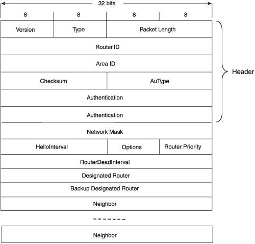
The Hello protocol also performs other functions such as the discovery and election of Designated Routers. The remainder of this chapter examines the similarities and differences in how OSPF and IS-IS implement the Hello protocol and defines functions that rely on the protocol such as the designated router function. 4.2.1. OSPF Hello Protocol BasicsFigure 4.9 diagrams the OSPF Hello message. Figure 4.9. The OSPF Hello message format.
When an OSPF router receives a Hello from an OSPF neighbor, it stores the information contained in the Hello in a neighbor database. The first output in Figure 4.10 displays one such database. As you can see from the first display, the router has three neighbors. The second output in Figure 4.10 displays the information from the neighbor whose RID is 192.168.254.2. In this second display, you can observe all the information learned from that neighbor's Hellos: the Priority, the remaining time before the advertised Router Dead Interval expires, the RID and AID from the packet header, the value of the Options field, and the addresses of the Designated Router and Backup Designated Router. Chapter 6 details the neighbor database, along with the various neighbor states.
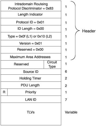
4.2.2. IS-IS Hello Protocol BasicsUnlike OSPF, which uses a single form of Hello message, IS-IS has three. First, a different form of Hello is used depending on whether it is being originated on a point-to-point (non-broadcast) link or a LAN (broadcast) link. On LAN links, the type of Hello varies depending upon whether a potential neighbor is in the same area (level 1) or in a different area (level 2). Which type of Hello is sent on a particular LAN link depends on the configuration of the router interface connecting to the link. The interface can be configured as L1-only, in which case Level 1 LAN Hellos are sent, or as L2-only, in which case Level 2 LAN Hellos are sent. A LAN interface can also be both L1 and L2, in which case both types of Hellos are sent. The reason for this is that a router might find multiple neighbors on a single broadcast link. Some of the neighbors might have the same area ID, in which case an L1 adjacency will be established. Other neighbors might have different area IDs, in which case L2 adjacencies will be established. Point-to-point links have, by definition, only a single neighbor, so there will only be an L1 or L2 adjacency or, at most, one L1 and one L2 adjacency. An interface connecting to a point-to-point link should be configured accordingly. A single Point-to-Point Hello is used for both L1 and L2 adjacencies. Figure 4.11 shows the format of the IS-IS LAN Hello. Note that the Type field in the header indicates whether the LAN Hello is level 1 or level 2. L1 LAN Hellos are type 15 (0x0f), and L2 LAN Hellos are type 16 (0x10). Figure 4.11. The IS-IS LAN Hello PDU format.
The values shown in Table 4.1 have some interesting implications. The first is that a router sending L2 LAN Hellos can establish both L1 and L2 adjacencies. The second is that two L2-only neighbors with the same AID (and therefore in the same area) can establish an L2 adjacency, so that only L2 information is exchanged. Chapter 7 discusses these capabilities in the context of IS-IS area design.
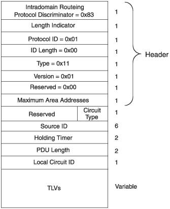
Figure 4.12 shows the format of the IS-IS Point-to-Point Hello (type 17, or 0x11, in the Type field). The Hello looks very similar to the LAN Hello, with just two exceptions:
Figure 4.12. The IS-IS Point-to-Point Hello PDU format. 4.2.2.1. TLVsFollowing the common fields in the IS-IS Hello PDUs are several possible TLVs. The TLVs that can be included in the Hello PDUs, and their type numbers, are:
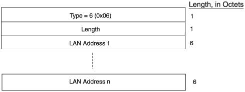
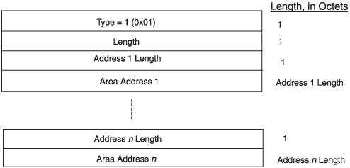
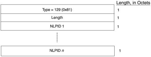
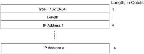
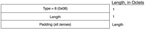
The LAN Hello PDU can carry any or all of these TLVs, and the Point-to-Point Hello can carry any of them with the exception of the IS Neighbors TLV. Two of the TLVs, Protocols Supported and IP Interface Address, are IP extensions to IS-IS and are described in RFC 1195. The others are standard IS-IS TLVs described in the original specifications. A few other TLVs might also appear in IS-IS Hellos; they are discussed later in this book in relevant chapters on extensions to the protocol. The Area Addresses TLV, shown in Figure 4.13, contains in its Variable part a list of AIDs configured on the originating router that must be advertised to neighbors. The fact that more than one AID can be listed in this TLV tells you that an IS-IS router can be configured with more than one AID. The multiple AID capability of IS-IS can be used for smoothly changing AIDs during a network transition. Chapter 7 discusses the use of multiple AIDs. Figure 4.13. The Area Addresses TLV. The Intermediate System Neighbors TLV, in Figure 4.14, lists neighbors on the link, by the MAC addresses of their attached interfacesor subnetwork points of attachment (SNPAs), in IS-IS language. In this function, the IS Neighbors TLV serves something of the same purpose as the Neighbor list in the OSPF Hello, to create a three-way handshake for verifying bidirectional communication. For an originating router to include a neighbor's MAC address in this TLV, the originator must have received a LAN Hello from the neighbor during the last holding time. In that case, the state of the adjacency to the neighbor will be either "Up" or "Initializing." (See Section 4.4 for more details.) Level 1 LAN Hellos list L1 neighbors and level 2 LAN Hellos list L2 neighbors. Point-to-Point Hellos do not carry this TLV, which means some other mechanism must be used for three-way handshaking. Section 4.4 discusses the other means. Figure 4.14. The Intermediate System Neighbors TLV. The Protocols Supported TLV, shown in Figure 4.15, specifies, as the name implies, which protocols the originating router supports. It lists one or more Network Layer Protocol Identifiers (NLPIDs), which are defined in ISO/TR 9577 and in several extension documents. Because IS-IS originally was designed to route just CLNP, this TLV was added when the protocol was extended to support IP. With it, the originator can advertise whether it supports Figure 4.15. The Protocols Supported TLV. CLNP only, IPv4 only, or both. With the subsequent extension of IS-IS to support IPv6, as described in Chapter 13, that protocol also is listed in the Protocols Supported TLV when the originator uses IS-IS to route IPv6. The NLPID of IPv4 is 129 (ox81), and the NLPID of IPv6 is 142 (0x8e). The IP Interface Address TLV, in Figure 4.16, lists all the IP addresses of the interface from which the Hello was originated. Although in most cases an interface will have only one address, it is possible to configure multiple IP addresses on an interface. Because the length field of the TLV, which specifies the byte length of the value field, is 1 byte, and because each listed IP address is 4 bytes long, the maximum number of IP addresses that can be listed in the TLV is 63. Figure 4.16. The IP Interface Address TLV. The Authentication Information TLV carries information to be used when the router is configured to authenticate PDUs to and from its IS-IS neighbors. This TLV is illustrated in Chapter 9, which discusses protocol security. After two neighbors have discovered each other, one of the parameters they must verify before they can become adjacent is that the maximum transmission units (MTUs)[2] of their two interfaces are compatible. For example, if one interface has an MTU of 1000 bytes and the other 1500 bytes, the router with the 1500-byte MTU might send routing messages larger than the router with the smaller MTU can receive. The result would be dropped messages, lost information, and probably broken adjacencies. So, there must be a way for two neighbors to verify that their MTUs are compatible before forming an adjacency. OSPF routers advertise their interface MTUs in their Database Description messages, as described in Chapter 5, and refuse adjacencies unless the MTU values of the two neighbors match. IS-IS tests the link MTU between neighbors by padding their Hello packets out to a maximally acceptable size, using Padding TLVs (Figure 4.17).
Figure 4.17. The Padding TLV. The value of the Padding TLV consists of some quantity of 0s, which are ignored by receiving routers. The only purpose of the TLV is to increase the size of the PDU containing it. ISO 10589 specifies that IS-IS routers must be capable of receiving PDUs of at least 1492 bytes in lengtha value it calls ReceiveLSPBufferSize. When a router sends Hellos, it uses the Padding TLV to increase the size of the Hello PDU either to this size, or to the MTU of the connecting link, whichever is greater. As a result, if the neighboring router has a lower interface MTU, it drops the padded Hellos, and an adjacency is never established. Because of the 1-byte length field in the TLV, the maximum size of the value field is 255. Because of this, IS-IS routers will add multiple Padding TLVs to their Hellos to reach the needed size. Also note that padded Hellos are needed only when an adjacency is first being negotiated. After it is established, continuing to pad the Hellos between adjacent neighbors is just a waste of bandwidth. As a result, smart IS-IS implementations pad only the first few Hellos. When the adjacency is established, padding is discontinued. Figure 4.18 shows an IS-IS neighbor table, functionally analogous to the OSPF neighbor table shown in Figure 4.10. The first display shows that the router has three IS-IS neighbors.
The second display focuses on one of those neighbors, and you can observe information learned from the neighbor's Hellos:
4.2.3. IS-IS Dynamic Hostname ExchangeA perhaps surprising detail in Figure 4.18 is that where you would expect a SysID to be displayedunder the System heading in the first output and as the first part of the LAN ID in the second outputthere is instead a host name. This is the result of an extension to ISIS called the Dynamic Hostname Exchange Mechanism, described in RFC 2763. The RFC defines a new TLV, called the Dynamic Hostname TLV (type 137), which a router can add to its LSPs. The value field of the TLV contains an ASCII text name of the router, which is usually just the configured host name of the router. When other routers in the IS-IS domain receive the LSP, they can map the name contained in the TLV with the SysID of the originating router, and store the information in a host name mapping table. Figure 4.19 shows a host name mapping table taken from the same router as the display in Figure 4.18. You can see that this router contains five SysID-to-name mappings, including its own (indicated as a static, rather than dynamic, mapping). The advantages for network operations, maintenance, and troubleshooting of having an easily understood name in the place of cryptic hex-based SysIDs in displays such as the one in Figure 4.18 are readily apparent.
4.2.4. OSPF Domain Name LookupSome OSPF implementations support a feature similar to IS-IS Dynamic Host Name Lookup. Although the benefits are the sameproviding names rather than addresses in OSPF displays to simplify activitiesthe feature operates very differently. Instead of carrying configured names as ASCII text in messages, the router attempts to resolve the IP addresses of OSPF displays in DNS. If you have entered all loopback addresses, RIDs, and interface addresses in your local DNS, this utility can show these by name instead of numerically. However, there is no IETF extension of OSPF to support this feature, as there is for IS-IS dynamic host names. Rather, if it is supported it is a feature added by an implementer. A potential liability of this OSPF feature, when it is supported, is that the DNS lookup is independent of OSPF itself and dependent upon the availability of a DNS server. So if a name cannot be resolved quickly, or the DNS server becomes unavailable, your router might become slow to respond to requests for OSPF displays as it waits for DNS. The very time you most need OSPF information displays from a routerduring network outagesis also a time that a DNS server is likely to become unavailable. This scenario should be a consideration in whether to use the utility. In most cases, the day-to-day usefulness of OSPF name lookups outweighs possible problems with it. And, if the feature should create problems for you, DNS name lookups can be easily disabled on the router until the DNS server is again available. |
EAN: 2147483647
Pages: 111