Troubleshooting OSPF
| Troubleshooting OSPF can sometimes be daunting, especially in a large network. However, a routing problem with OSPF is no different than a routing problem with any other routing protocol; the cause will be one of the following:
An examination of the route table is still the primary source of troubleshooting information. Using the show ip ospf database command to examine the various LSAs will also yield important information. For example, if a link is unstable, the LSA advertising will change frequently. This condition is reflected in a sequence number that is conspicuously higher than that of the other LSAs. Another sign of instability is an LSA whose age never gets very high. Keep in mind that the link-state database of every router within an area is the same. So unless you suspect that the database itself is being corrupted on some routers, you can examine the link-state database for the entire area by examining a single router's link-state database. Another good practice is to keep a copy (hard or soft) of the link-state database for each area. When examining an individual router's configuration, consider the following:
When examining adjacencies (or the lack thereof), consider these questions:
If a neighbor or adjacency is suspected of being unstable, adjacencies can be monitored with the command debug ip ospf adj. However, this command can often present more information than you want, as Example 8-96 shows. The state changes of a neighbor are recorded in great detail. If monitoring is to be performed over an extended period, this wealth of information can overflow a router's internal logging buffers. Beginning with IOS 11.2, adjacencies can be monitored by adding the command log-adjacency-changes [detail] under a router's OSPF configuration. This command will keep a simpler log of adjacency changes, as shown in Example 8-97 and Example 8-98. Example 8-96. This debug output from debug ip ospf adj shows the result of temporarily disconnecting and then reconnecting a neighbor's Ethernet interface.%LINEPROTO-5-UPDOWN: Line protocol on Interface Ethernet0/0, changed state to down OSPF: Interface Ethernet0/0 going Down OSPF: 172.16.2.2 address 10.8.1.1 on Ethernet0/0 is dead, state DOWN OSPF: Neighbor change Event on interface Ethernet0/0 OSPF: DR/BDR election on Ethernet0/0 OSPF: Elect BDR 0.0.0.0 OSPF: Elect DR 172.16.2.3 OSPF: Elect BDR 0.0.0.0 OSPF: Elect DR 172.16.2.3 DR: 172.16.2.3 (Id) BDR: none OSPF: 172.16.2.3 address 10.8.1.2 on Ethernet0/0 is dead, state DOWN OSPF: Neighbor change Event on interface Ethernet0/0 OSPF: DR/BDR election on Ethernet0/0 OSPF: Elect BDR 0.0.0.0 OSPF: Elect DR 0.0.0.0 DR: none BDR: none OSPF: Remember old DR 172.16.2.3 (id) OSPF: Build router LSA for area 0, router ID 172.16.2.2, seq 0x80000035 OSPF: Build router LSA for area 25, router ID 172.16.2.2, seq 0x80000005 %LINEPROTO-5-UPDOWN: Line protocol on Interface Ethernet0/0, changed state to up OSPF: Interface Ethernet0/0 going Up OSPF: Send with youngest Key 5 OSPF: Build router LSA for area 0, router ID 172.16.2.2, seq 0x80000036 OSPF: Build router LSA for area 25, router ID 172.16.2.2, seq 0x80000006 OSPF: Send with youngest Key 5 OSPF: Send with youngest Key 5 OSPF: Send with youngest Key 5 OSPF: Rcv DBD from 172.16.2.3 on Ethernet0/0 seq 0x728 opt 0x52 flag 0x7 len 32 mtu 1500 state INIT OSPF: 2 Way Communication to 172.16.2.3 on Ethernet0/0, st ate 2WAY OSPF: Nbr state is 2WAY OSPF: Rcv DBD from 172.16.2.3 on Ethernet0/0 seq 0x728 opt 0x52 flag 0x7 len 32 mtu 1500 state 2WAY OSPF: Nbr state is 2WAY OSPF: end of Wait on interface Ethernet0/0 OSPF: DR/BDR election on Ethernet0/0 OSPF: Elect BDR 172.16.2.2 OSPF: Elect DR 172.16.2.3 OSPF: Elect BDR 172.16.2.2 OSPF: Elect DR 172.16.2.3 DR: 172.16.2.3 (Id) BDR: 172.16.2.2 (Id) OSPF: Send DBD to 172.16.2.3 on Ethernet0/0 seq 0x1B85 opt 0x52 flag 0x7 len 32 OSPF: Send with youngest Key 5 OSPF: Send with youngest Key 5 OSPF: Rcv DBD from 172.16.2.3 on Ethernet0/0 seq 0x728 opt 0x52 flag 0x7 len 32 mtu 1500 state EXSTART OSPF: NBR Negotiation Done. We are the SLAVE OSPF: Send DBD to 172.16.2.3 on Ethernet0/0 seq 0x728 opt 0x52 flag 0x2 len 292 OSPF: Send with youngest Key 5 OSPF: Rcv DBD from 172.16.2.3 on Ethernet0/0 seq 0x729 opt 0x52 flag 0x3 len 272 mtu 1500 state EXCHANGE OSPF: Send DBD to 172.16.2.3 on Ethernet0/0 seq 0x729 opt 0x52 flag 0x0 len 32 OSPF: Send with youngest Key 5 OSPF: Send with youngest Key 5 OSPF: Database request to 172.16.2.3 OSPF: sent LS REQ packet to 10.8.1.2, length 12 OSPF: Send with youngest Key 5 OSPF: Rcv DBD from 172.16.2.3 on Ethernet0/0 seq 0x72A opt 0x52 flag 0x1 len 32 mtu 1500 state EXCHANGE OSPF: Exchange Done with 172.16.2.3 on Ethernet0/0 OSPF: Send DBD to 172.16.2.3 on Ethernet0/0 seq 0x72A opt 0x52 flag 0x0 len 32 OSPF: Send with youngest Key 5 OSPF: Synchronized with 172.16.2.3 on Ethernet0/0, state FULL OSPF: Build router LSA for area 0, router ID 172.16.2.2, seq 0x80000037 Example 8-97. These logging messages, resulting from the OSPF configuration command log-adjacency-changes, show the same neighbor failure as depicted in Example 8-96, but with much less detail.Hurd#show logging Syslog logging: enabled (0 messages dropped, 1 messages rate-limited, 0 flushes, 0 overruns, xml disabled) Console logging: level debugging, 248 messages logged, xml disabled Monitor logging: level debugging, 0 messages logged, xml disabled Buffer logging: level debugging, 5 messages logged, xml disabled Logging Exception size (4096 bytes) Count and timestamp logging messages: disabled Trap logging: level informational, 99 message lines logged Log Buffer (4096 bytes): %OSPF-5-ADJCHG: Process 1, Nbr 172.16.2.3 on Ethernet0/0 from FULL to DOWN, Neighbor Down: Interface down or detached %OSPF-5-ADJCHG: Process 1, Nbr 172.16.2.3 on Ethernet0/0 from LOADING to FULL, Loading DoneExample 8-98. These logging messages, resulting from the OSPF configuration command log-adjacency-changes also show the same neighbor failure as depicted in Example 8-96, but have more detail than the log in Example 8-97.Hurd#show logging Syslog logging: enabled (0 messages dropped, 1 messages rate-limited, 0 flushes, 0 overruns, xml disabled) Console logging: level debugging, 248 messages logged, xml disabled Monitor logging: level debugging, 0 messages logged, xml disabled Buffer logging: level debugging, 5 messages logged, xml disabled Logging Exception size (4096 bytes) Count and timestamp logging messages: disabled Trap logging: level informational, 99 message lines logged Log Buffer (4096 bytes): %OSPF-5-ADJCHG: Process 1, Nbr 172.16.2.3 on Ethernet0/0 from FULL to DOWN, Neighbor Down: Interface down or detached %OSPF-5-ADJCHG: Process 1, Nbr 172.16.2.3 on Ethernet0/0 from DOWN to INIT, Received Hello %OSPF-5-ADJCHG: Process 1, Nbr 172.16.2.3 on Ethernet0/0 from INIT to 2WAY, 2-Way Received %OSPF-5-ADJCHG: Process 1, Nbr 172.16.2.3 on Ethernet0/0 from 2WAY to EXSTART, AdjOK? %OSPF-5-ADJCHG: Process 1, Nbr 172.16.2.3 on Ethernet0/0 from EXSTART to EXCHANGE, Negotiation Done %OSPF-5-ADJCHG: Process 1, Nbr 172.16.2.3 on Ethernet0/0 from EXCHANGE to LOADING, Exchange Done %OSPF-5-ADJCHG: Process 1, Nbr 172.16.2.3 on Ethernet0/0 from LOADING to FULL, Loading DoneIf you suspect that a link-state database is corrupted or that two databases are not synchronized, you can use the show ip ospf database database-summary command to observe the number of LSAs in each router's database. For a given area, the number of each LSA type should be the same in all routers. Next, the command show ip ospf database will show the checksums for every LSA in a router's database. Within a given area, each LSA's checksum should be the same in every router's database. Verifying this status can be excruciatingly tedious for all but the smallest databases. Luckily, there are MIBs,[34] which can report the sum of a database's checksums to an SNMP management platform. If all databases in an area are synchronized, this sum should be the same for each database.
When examining an area-wide problem, consider the following issues:
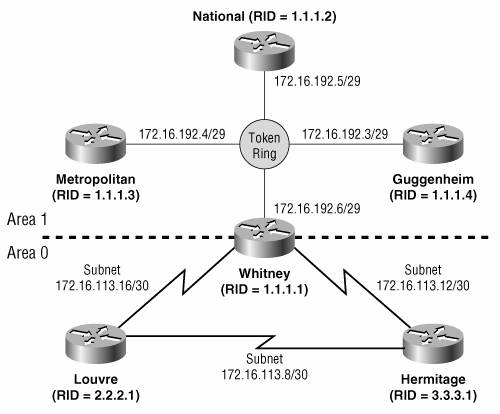
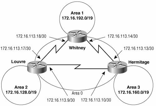
If performance is a problem, check the memory and CPU utilization on the routers. If memory utilization is above 70 percent, the link-state database might be too large; if CPU utilization is consistently above 60 percent, instabilities could exist in the topology. If memory or CPU surpasses the 50 percent mark, the network administrator should analyze the cause of the performance stress and, based on the results of the analysis, should begin planning corrective upgrades. Stub areas and address summarization can help to both reduce the size of the link-state database and to contain instabilities. The processing of LSAs, not the SPF algorithm, puts the most burden on an OSPF router. Taken individually, type 1 and type 2 LSAs would be more processor-intensive than summary LSAs. However, type 1 and 2 LSAs tend to be grouped, whereas summary LSAs are sent in individual packets. As a result, in reality, summary LSAs are more processor-intensive. The following case studies demonstrate the most frequently used techniques and tools for troubleshooting OSPF. Case Study: An Isolated AreaIntra-area packets can be routed within area 1 of Figure 8-54, but all attempts at inter-area communications fail. Suspicion should immediately fall on area 1's ABR. This suspicion is reinforced by the fact that the Internal Routers have no router entry for an ABR (Example 8-99). Figure 8-54. The end systems and routers within area 1 can communicate, but no traffic is being passed to or from area 0. Example 8-99. The command show ip ospf border-routers checks the internal route table of the Internal Routers. No router entry for an ABR is shown.National#show ip ospf border-routers OSPF Process 8 internal Routing Table Codes: i - Intra-area route, I - Inter-area route National#The next step is to verify that the physical link to the ABR is operational and that OSPF is working properly. The same Internal Router's neighbor table (Example 8-100) shows that the neighbor state of the ABR is full, indicating that an adjacency exists. In fact, the ABR is the DR for the Token Ring network. The existence of an adjacency confirms that the link is good and that OSPF Hellos are being exchanged with the proper parameters. Example 8-100. The neighbor table of router National indicates that the ABR (1.1.1.1) is fully adjacent.National#show ip ospf neighbor Neighbor ID Pri State Dead Time Address Interface 1.1.1.1 1 FULL/DR 00:00:33 172.16.192.6 TokenRing0 1.1.1.3 1 FULL/BDR 00:00:34 172.16.192.4 TokenRing0 1.1.1.4 1 FULL/ - 00:00:30 172.16.192.3 TokenRing0 National# Other evidence relevant to the problem can be found in National's database and its route table. The database (Example 8-101) contains only Router (type 1) and Network (type 2) LSAs. No Network Summary (type 3) LSAs, which advertise destinations outside of the area, are recorded. At the same time, there are LSAs originated by Whitney (1.1.1.1). This information again indicates that Whitney is adjacent but is not passing information from area 0 into area 1. Example 8-101. National's link-state database also shows that Whitney is adjacent, but is not advertising inter-area destinations.National#show ip ospf database OSPF Router with ID (1.1.1.2) (Process ID 8) Router Link States (Area 1) Link ID ADV Router Age Seq# Checksum Link count 172.16.192.6 1.1.1.1 132 0x80000034 0xAC4D 3 172.16.219.120 1.1.1.2 1 458 0x8000002B 0x6B46 2 Net Link States (Area 1) Link ID ADV Router Age Seq# Checksum 172.16.192.6 1.1.1.1 132 0x8000002E 0x2078 National#The only destinations outside of area 1 in National's route table (Example 8-102) are the serial links attached to Whitney. Yet another clue is revealed here: The route entries are tagged as intra-area routes (O); if they were in area 0, as Figure 8-54 shows they should be, they would be tagged as inter-area routes (O IA). The problem is apparently on the area 0 side of the ABR. Example 8-102. Whitney is advertising the subnets of its serial interfaces, but they are being advertised as intra-area destinations.National#show ip route Codes: C - connected, S - static, R - RIP, M - mobile, B BGP D - EIGRP, EX - EIGRP external, O - OSPF, IA - OSPF inter area N1 - OSPF NSSA external type 1, N2 - OSPF NSSA external type 2 E1 - OSPF external type 1, E2 - OSPF external type 2 i - IS-IS, su - IS-IS summary, L1 - IS-IS level-1, L2 - IS-IS level-2 ia - IS-IS inter area, * - candidate default, U - per-user static route o - ODR, P - periodic downloaded static route Gateway of last resort is not set 172.16.0.0/16 is variably subnetted, 4 subnets, 3 masks C 172.16.219.112/28 is directly connected, Serial0 C 172.16.192.0/29 is directly connected, TokenRing0 O 172.16.113.12/30 [110/70] via 172.16.192.6, 09:32:15, TokenRing0 O 172.16.113.16/30 [110/70] via 172.16.192.6, 09:32:15, TokenRing0 National# An examination of Whitney's serial interfaces (Example 8-103) reveals the problem, if not the cause of the problem. Both interfaces, which should be in area 0, are instead in area 1. Both interfaces are connected to topological neighbors (Louvre and Hermitage), but no OSPF neighbors are recorded. Error messages are being displayed regularly, indicating that Whitney is receiving Hellos from Louvre and Hermitage; those Hellos have their Area fields set to zero, causing a mismatch. Example 8-103. Whitney's serial interfaces are configured in area 1 instead of area 0; this configuration is causing error messages when area 0 Hellos are received.Whitney#show ip ospf interface serial 0 Serial0 is up, line protocol is up Internet Address 172.16.113.18/30, Area 1 Process ID 8, Router ID 1.1.1.1, Network Type POINT_TO_POINT, Cost: 64 Transmit Delay is 1 sec, State POINT_TO_POINT, Timer intervals configured, Hello 10, Dead 40, Wait 40, Retransmit 5 oob-resync timeout 40 Hello due in 00:00:03 Index 1/3, flood queue length 0 Next 0x0(0)/0x0(0) Last flood scan length is 2, maximum is 2 Last flood scan time is 0 msec, maximum is 0 msec Neighbor Count is 0, Adjacent neighbor count is 0 Suppress hello for 0 neighbor(s) Whitney#show ip ospf interface serial 1 Serial0 is up, line protocol is up Internet Address 172.16.113.14/30, Area 1 Process ID 8, Router ID 1.1.1.1, Network Type POINT_TO_POINT, Cost: 64 Transmit Delay is 1 sec, State POINT_TO_POINT, Timer intervals configured, Hello 10, Dead 40, Wait 40, Retransmit 5 oob-resync timeout 40 Hello due in 00:00:06 Index 1/3, flood queue length 0 Next 0x0(0)/0x0(0) Last flood scan length is 2, maximum is 2 Last flood scan time is 0 msec, maximum is 0 msec Neighbor Count is 0, Adjacent neighbor count is 0 Suppress hello for 0 neighbor(s) Whitney# %OSPF-4-ERRRCV: Received invalid packet: mismatch area ID, from backbone area must be virtual-link but not found from 172.16.113.13, Serial1 %OSPF-4-ERRRCV: Received invalid packet: mismatch area ID, from backbone area must be virtual-link but not found from 172.16.113.17, Serial0 Whitney's OSPF configuration is shown in Example 8-104. Example 8-104. Whitney's OSPF configuration.router ospf 8 network 172.16.0.0 0.0.255.255 area 1 network 172.16.113.0 0.0.0.255 area 0 At first glance, this configuration might appear to be fine. However, recall from the first configuration case study that the network area commands are executed consecutively. The second network area command affects only interfaces that do not match the first command. With this configuration, all interfaces match the first network area command and are placed into area 1. The second command is never applied. A correct configuration is shown in Example 8-105. Example 8-105. Whitney's corrected OSPF configuration.router ospf 8 network 172.16.192.0 0.0.0.255 area 1 network 172.16.113.0 0.0.0.255 area 0 There are, of course, several valid configurations. The important point is that the first network area command must be specific enough to match only the address of the area 1 interface, and not the addresses of the area 0 interfaces. Case Study: Misconfigured SummarizationFigure 8-55 shows a backbone area and three attached areas. To reduce the size of the link- state database and to increase the stability of the network, summarization will be used between areas. Figure 8-55. The summary addresses shown for each area will be advertised into area 0. Area 0 will also be summarized into the other areas. The individual subnets of the three nonbackbone areas are summarized with the addresses shown in Figure 8-55. For example, a few of the subnets of area 1 may be
Figure 8-56 shows that these subnet addresses can all be summarized with 172.16.192.0/19. Figure 8-56. A few of the subnet addresses that are summarized with 172.16.192.0/19. The bold type indicates the network bits of each address.
Whitney's configuration is shown in Example 8-106 Example 8-106. Whitney's OSPF configuration with address summarization.router ospf 8 network 172.16.192.0 0.0.0.255 area 1 network 172.16.113.0 0.0.0.255 area 0 area 1 range 172.16.192.0 255.255.224.0 area 0 range 172.16.113.0 255.255.224.0 The other three ABRs are configured similarly. Each ABR will advertise the summary address of its attached non-backbone area into area 0 and will also summarize area 0 into the non-backbone area. Example 8-107 shows that there is a problem. When the route table of one of area 1's Internal Routers is examined, area 0 is not being summarized properly (area 1's internal subnets are not shown, for clarity). Although the summary addresses for areas 2 and 3 are present, the individual subnets of area 0 are in the table instead of its summary address. Example 8-107. The individual subnets of area 0, instead of the expected summary address, are recorded in the route table of one of area 1's internal routers.National#show ip route Codes: C - connected, S - static, R - RIP, M - mobile, B BGP D - EIGRP, EX - EIGRP external, O - OSPF, IA - OSPF inter area N1 - OSPF NSSA external type 1, N2 - OSPF NSSA external type 2 E1 - OSPF external type 1, E2 - OSPF external type 2 i - IS-IS, su - IS-IS summary, L1 - IS-IS level-1, L2 - IS-IS level-2 ia - IS-IS inter area, * - candidate default, U - per-user static route o - ODR, P - periodic downloaded static route Gateway of last resort is not set 172.16.0.0/16 is variably subnetted, 7 subnets, 4 masks O IA 172.16.160.0/19 [110/80] via 172.16.192.6, 09:32:15, TokenRing0 O IA 172.16.128.0/19 [110/80] via 172.16.192.6, 09:32:15, TokenRing0 C 172.16.192.0/29 is directly connected, TokenRing0 O IA 172.16.113.12/30 [110/70] via 172.16.192.6, 09:32:15, TokenRing0 O IA 172.16.113.8/30 [110/134] via 172.16.192.6, 09:32:15, TokenRing0 O IA 172.16.113.16/30 [110/70] via 172.16.192.6, 09:32:15, TokenRing0 National# You can see that the area range command for area 0 is the problem when you examine the three subnets of area 0 in binary (Figure 8-57). Figure 8-57. The subnets of area 0, the configured summary mask, and the correct summary address.
The problem is that the summary address specified in the area range command (172.16.113.0) is more specific than the accompanying mask (255.255.224.0). The correct address to use with the 19-bit mask is 172.16.96.0 (see Example 8-108). Example 8-108. Whitney's OSPF configuration with corrected address summarization.router ospf 8 network 172.16.192.0 0.0.0.255 area 1 network 172.16.113.0 0.0.0.255 area 0 area 1 range 172.16.192.0 255.255.224.0 area 0 range 172.16.96.0 255.255.224.0 Example 8-109 shows the resulting route table. There are other options for area 0's summary address. For example, 172.16.113.0/24 and 172.16.113.0/27 are both legitimate. The most appropriate summary address depends on the priorities of the network design. In the case of the network of Example 8-101, 172.16.96.0/19 might be selected for consistencyall summary addresses have a 19-bit mask. On the other hand, 172.16.113.0/27 might be selected for better scalability; five more subnets can be added to the backbone under this summary address, leaving a wider range of addresses to be used elsewhere in the network. Example 8-109. Area 0 is now being summarized correctly.National#show ip route Codes: C - connected, S - static, R - RIP, M - mobile, B BGP D - EIGRP, EX - EIGRP external, O - OSPF, IA - OSPF inter area N1 - OSPF NSSA external type 1, N2 - OSPF NSSA external type 2 E1 - OSPF external type 1, E2 - OSPF external type 2 i - IS-IS, su - IS-IS summary, L1 - IS-IS level-1, L2 - IS-IS level-2 ia - IS-IS inter area, * - candidate default, U - per-user static route o - ODR, P - periodic downloaded static route Gateway of last resort is not set 172.16.0.0/16 is variably subnetted, 5 subnets, 3 masks O IA 172.16.160.0/19 [110/80] via 172.16.192.6, 00:25:09, TokenRing0 O IA 172.16.128.0/19 [110/80] via 172.16.192.6, 09:32:15, TokenRing0 C 172.16.192.0/29 is directly connected, TokenRing0 O IA 172.16.96.0/19 [110/70] via 172.16.192.6, 00:00:10, TokenRing0 National# |
EAN: 2147483647
Pages: 233