2.4 Big Things: Packages, Components, and Subsystems
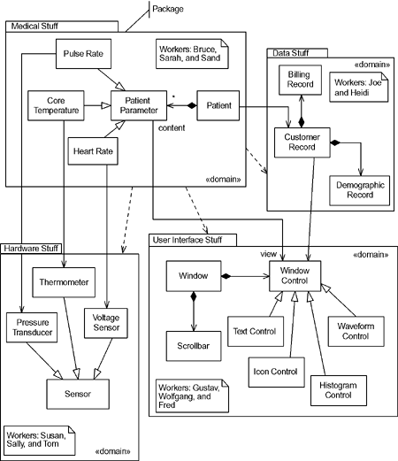
| Classes, objects, and interfaces are usually little things. It takes collaborations of many of them to achieve system-wide behavior. Because of the complexity of today's systems, it is unusual to find a system that can be effectively developed and managed without thinking about larger-scale structures. The UML does provide a number of concepts to manage systems in the large scale (all based on the concept of a class), although most of the literature has not effectively explained or demonstrated the use of these features. "Big things" come in two primary flavors to reflect the two common scalability problems in building real systems. The first is the issue of organizing a model, keeping track of hundreds or thousands of classes, and effectively sharing the work among many different developers, possibly geographically separated. The model management question is primarily addressed with the UML concept of packages, as we will see in the next section. The other scalability concept is for large runtime things. If I'm building a spacecraft, I need to think at many different levels of abstraction. I might have a use case (system capability) like "Go get a rock on Mars" and this will involve potentially millions of things at the most primitive scale. I would like to think about the roles of the deep space network, the launch vehicle, the orbiter, the lander, Mission Control, and so on. These elements are BIG, each containing thousands of parts. In the design of the spacecraft, I may want to consider large-scale things such as the navigation system, attitude control, the communications system, hydraulics, power control, life support, thermal management, and so on. Each of these things is likewise BIG (although only a piece of the largest-scale things in the system to be considered), also containing potentially thousands of simple parts. And so on until we get down to the level of simple individual sensors, switches, messages, waypoints, batteries, and the like. We need some way to think about large-scale elements that exist at runtime that are composed of parts, which may themselves contain smaller parts. The UML 2.0 specification refines the concepts of component and subsystem, and even class, for this purpose. These concepts will be discussed after we discuss the easier issue of packages and model management. 2.4.1 Model Organization: PackagesPackages are (design-time) model elements that can contain other model elements, including other packages. Packages are used to sub divide models to permit teams of developers to manipulate and work effectively together. Packages cannot be instantiated and can only be used to organize models. They do define a namespace for the model elements that they contain, but no other semantics. The UML does not provide any criterion as to whether a class should go in this package or that it merely provides packages as model-building blocks to aid in whatever organizational purpose the developer desires. The ROPES process recommends that packages be used with a specific criterion "common subject matter or common vocabulary." This is similar to the Shaler and Mellor concept of a domain, and the ROPES process uses the stereotype «domain» to indicate this particular usage of packages. However, packages can be used to organize the application model in just about any desired way. A package normally contains elements that exist only at design-time classes and data types but may also contain use cases and various diagrams, such as sequence and class diagrams. These design pieces are then used to construct collaborations that realize system-wide functionality. Packages are normally the basic configuration items for a configuration management tool, rather than the individual classes. Figure 2-11 shows that packages are drawn to look like a tabbed folder and may optionally show elements that they semantically contain. In this figure, there are four packages Medical Stuff, Data Stuff, User Interface Stuff, and Hardware Stuff. Each class in the system resides in a single package, although it may be referenced by elements of other packages. In fact, we see many associations from elements in one package to elements in another, such as PatientParameter associating with WindowControl. This association allows the two classes to collaborate so that a WindowControl may display information held within the PatientParameter. A domain is organized around a single subject matter and vocabulary, such as user interface or hardware. All the classes that are within that subject matter are defined in the appropriate domain. Generalization taxonomies almost always fall within a single domain (a subclass of a window class is always a kind of window). If a class seems to fit in multiple domains, then it has too broad a scope and should be broken down into a set of collaborating classes, each of which fits in a single domain. Other strategies use packages with different rules about the elements they contain. Several different strategies are given in Chapter 1. Figure 2-11. Packages
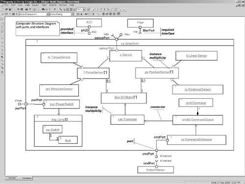
It is important to remember that packages have very little in the way of semantics. They define an enclosing namespace for the elements contained within them but that's all. They are not instantiable you can't point to a running system and point to an instance of a package. Packages are used to organize models for model management and are, therefore, design-time organizational concepts only. 2.4.2 Structured Classes: Composites, Parts, Ports, and ConnectorsSo far, we've considered classes only at the small end of the scale simple, primitive, and easy to implement. If only life could be so easy! However, it is necessary to concern ourselves as well with "designing in the large" and construct and manipulate classes that are not simple, primitive, and directly implemented. When we talk about nonprimitive things, we mean things that are defined in terms of smaller pieces. Structured classes (or more properly structured classifiers) are exactly that classes that contain an internal collaboration structure of Parts. Parts are instance roles linked together with Connectors (similar to links, but connect parts rather than objects). Structured classes are not any different than ordinary classes really, it's just that classes may be specified in terms of smaller, contained parts which themselves are typed by classes. There are a couple of special kinds of structured classifiers components and subsystems that carry particular meaning, but really it's all just classes. The concept of a structured class is based on both decomposition and encapsulation. The decomposition aspect is provided by the part objects contained within the structured class. In this case, we mean that the Smart Arm in Figure 2-12 is "rich" in the sense that it is internally implemented by the collaboration of its internal parts, including instances of CommandQueue, CommandController, ForceSensors, PositionSensors, Lamps, and so on. The structured class is not relegated to be a simple runtime container of these parts. Not only does it have the responsibility to create and destroy the part instances, it may also coordinate the activities and collaboration of these various part objects; when this is done, a statechart is normally created for the structured class to control and mediate the interaction of the parts. Figure 2-12. Structured Classes
The structured class itself is a class that owns its parts via the composition relation already discussed. For example, Figure 2-12 presents a structured class called Smart Arm. This robotic arm provides some set of services via the collaboration of its internal parts, such as instances of classes Controller, DCMotor, or Lamp. This use of the composition relation between the structured class and its parts implies several things. First, only a single structured class may own a specific part (instance of a contained class). Further, the structured class is responsible for the creation, destruction, and linking together of its parts. The number of instances of a Part held within a structured class is specified by its instance multiplicity. Instance multiplicity is the number of instances for a part within its context. There may be other instances that are parts of other structured classes (or even other instances of the same structured class), but they aren't considered in the multiplicity of a part within another class. There are two common forms for showing instance multiplicity. The first is to put the multiplicity in square brackets following the name of the class, as was done in Figure 2-12 for the DCMotor class. The other notation is to put the multiplicity in a corner of the part class as was done for the Controller class. If the multiplicity of a part is fixed, then those parts are made in the constructor of the structured class. For example, the seven DCMotors and the single Controller instances are made in the constructor of the SmartArm class. When the multiplicity of the part is variable (such as 0..4 or *) then the structured class typically does not create the parts in the structured class's constructor, but rather on as-needed basis during the execution of the structured class. Examples are the Command objects owned by the Command Queue. The parts within a structured class are linked together with connectors. A connector is a link, owned not by the part objects (which is the usual case with association instances), but rather, owned by the structured class. Each connector has two or more connector ends, each terminating on a part. The actual location of the connector end points forms the part topology of the structured class. The connectors are created by the structured class and link together the parts so that they can collaborate in the context of the structured class. The other key concept of structured classes is encapsulation of the class away from its environment. This is done through the use of ports, and offered and required interfaces. A structured class offers a set of services to its clients and in turn may levy requirements on its servers in the form of required interfaces. Some of these services are commands that can be sent to the Smart Arm via the iCommand interface, such as acceptCommand(c: Command) or reset(void). The acceptCommand (c: Command) operation is really defined on the part class called Command Scheduler. We would like this interface published across the encapsulation boundary defined by the Smart Arm, and we do this by defining a port to present that interface across this encapsulation boundary. Figure 2-12 provides a port that associates with an interface called iCommand. Note the use of the ball-and-socket notation for offered (ball) and required (socket) interfaces. This means that the client, Robot Planner, requires a specific set of services defined by iCommand to be met by a class, while the Smart Arm offers that same set of services. One can think of a port as a window placed on the boundary of a structured object to some specific internal feature that you want to make visible. The port delegates the operation on the edge of the structured class and redirects any message coming in to the internal part, or from that part out to an external object attached to the structured class via the port. Most commonly, a port is associated with either an offered or required interface, but a port is more general than that. Ports may be associated with either, neither, or both offered and required interfaces. Ports are said to be typed by their interfaces. It should be noted that ports, and even interfaces for that matter, are not required to build systems with structured classes. Using ports will usually introduce some runtime overhead and require additional memory. Since ports are not required, an operation of an internal part may be used directly by an external object (we call the structured class transparent in that case), although that tends to tightly couple the structured class internal structure with its environment. Ports and interfaces provide a convenient notation for specifying how a service offered from an internal part is published across the boundary of its enclosing structured class. As we will see in the next chapter, ports and interfaces may specify their behavior and sequencing constraints in protocol state machines so that we have the power to specify exactly how we want the operations published via the interfaces to work. The real power of structured classes is to enable the containment hierarchy of systems. That is, classes may contain internal parts, each of which may be decomposed into smaller parts, ad infinitum. This is necessary to model and manipulate models of large-scale real-time and embedded systems, from medical devices and aircraft to C4ISR[6] systems.
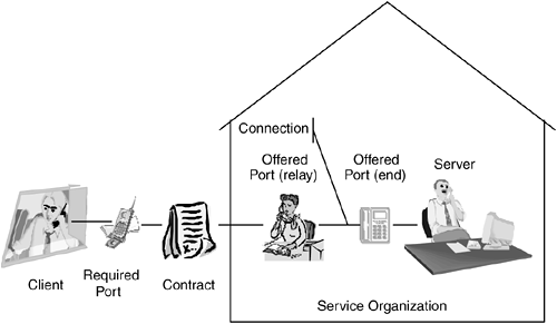
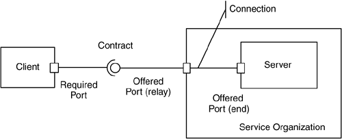
2.4.2.1 Ports: Connecting Outside the BoxPorts are different than interfaces in one important aspect ports are instantiable while interfaces are not. A port instance is a connection slot into an instance of a class that either relays a message to a part internal to the class (called a relay port) or accepts the message and hands it off to the object for handling (called an end or behavioral port). Since ports are instantiable, they have identity so that the class can tell which port provided the message. Since ports themselves may have behavior, they can mediate the handling of messages in a state-based way. An interface is a named collection of operations, but those operations are provided elsewhere. Interfaces have no behavior in and of themselves, they just allow a collection of services to be given a name. The required and offered aspects of the interface form a contract to which the client and server agree adhere. To get behavior, a class must realize the operations of the interface by providing matching methods that actually provide the services. An interface is like a phone book in that it names the services, while a port is like a telephone switchboard that handles the incoming messages and patches them through to where they need to go. Figure 2-13a shows metaphorically how I, at least, think of ports, interfaces, and connections. The interface is the contract, the rules by which you agree to abide, while the ports actually connect the plays (client and server) to invoke the services specified in the contract. In the example, the server is in fact a part of a larger service organization so that services requests are mediated by a relay port (our metaphorical secretary) but ultimately services requests are sent via the end port to the server. The connection is the infrastructure used to convey the messages (the phone lines in the metaphor). Figure 2-13b shows the UML notational equivalent for the metaphor. Figure 2-13a. Interfaces, Connections, and Ports (Semantic Metaphor)
Figure 2-13b. Interfaces, Connections, and Ports (UML Notation)
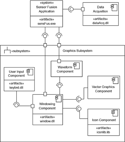
2.4.3 ComponentsNow we understand the basic concepts of a structured class as having parts connected, publishing services via interfaces, and providing runtime connections via ports. Any class can do this in the UML 2.0, but these notions relate very significantly to the concept of a UML component. In some sense, a UML component is merely a structured class with aspirations it is meant to be the primary replaceable unit of software a well-encapsulated piece of software that provides a coherent set of services, normally used and replaced together. There have been long and strenuous debates within the UML community over what constitutes a component versus a class, and how the specifically differ. The answer is that they don't, not really, but the term is so commonly used that relating concepts of structured classes to components used in the literature (and programming frameworks) is very helpful. As structured classes, components usually (but needn't necessarily) have interfaces and ports. To optimize a component for replaceability, encapsulating them away from their external environment is important and ports and interface help in this. In the UML 2.0 the notation for a component changed slightly, as shown in Figure 2-14. In UML 2.0, a component uses a box, just like a class, but can use either the stereotype «component» or the component icon inside the box. Figure 2-14. Components
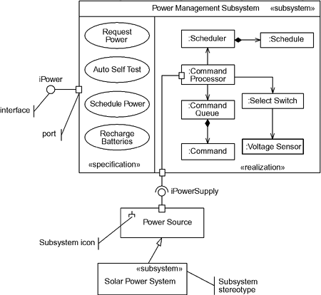
Note that some of the components have an «artifact» section. In UML 2.0, an artifact represents a piece of work created to deploy or represent information used in the systems or software development process. Documents, defect reports, Microsoft® Word documents, and computer files are all examples of artifacts. With components and other software entities on UML diagrams, the most common use for artifacts is to specify the unit of deployment of the software unit usually, although not limited to, a disk file. The identification of the implementing artifact is optional. In the example shown in Figure 2-14, the sensor fusion application consists of three primary pieces: the system (with the artifact senfus.exe), a data acquisition component (deployed in the artifact dataAcq.dll), and a graphics subsystem, which is further decomposed into several components. These components (and the subsystem) are all elements of the system structural architecture. These elements are each not primitive, but are internally decomposed into smaller pieces, and some of those may themselves be decomposed as well. In fact, it is common for components to contain (i.e., be composed of) smaller components just as structured classes may contain parts which are themselves structured classes. Just as a component is really nothing more than a class at the architectural level, this component diagram is nothing more than a class diagram that emphasizes the component architecture of the system. Frequently, component-based systems are built on a commercial or at least standardized component framework, such as Enterprise Java Beans (EJB), COM+, .NET, or the CORBA Component Model (CCM). Such component frameworks provide a standardized set of services (such as COM+ iUnknown interface for component identification) and the ability to load, unload, and otherwise manage components at runtime. This is not required to use the UML component concept, but the UML is consistent with those infrastructures. It is also common to construct real-time and embedded systems with custom component frameworks. 2.4.4 SubsystemsSubsystems are used to decompose the physical organization of large-scale systems at the highest level of abstraction. Figure 2-14 included an example of a subsystem, shown using both the stereotype «subsystem» and the icon (an inverted two-pronged fork). Like components, subsystems are architectural-level structured classes, and as such may have ports, and interfaces, and are decomposed into smaller parts. In the UML 2.0, in fact, a subsystem is a specialized kind of component (formally speaking, a stereotype), one that also includes a packaging name space. In actual usage, there is little to distinguish subsystems from components. Various notations for subsystems are shown in Figure 2-15. The Power Subsystem is shown with a stereotype and two subdivisions, one for specification (containing the specifying use cases) and one for realization (containing the parts that implement the subsystem specification). Either or both of these compartments may be suppressed as desired. The Power Source subsystem uses a subsystem stereotype icon (the inverted fork) rather than the textual stereotype and doesn't show any of its contents. In the figure, subsystems have both ports and interfaces, and while the use of interfaces is strongly encouraged, they are not required. Figure 2-15. Subsystems
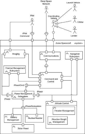
The next figure, Figure 2-16, provides an example of a subsystem diagram. In this diagram, a system object (the spacecraft) is shown with its internal subsystem parts. Of course, these subsystems are large and complex and are, no doubt, decomposed at least one or two more levels, if not more. In addition, exposed interfaces and ports are shown, along with the actors that interact with the system. However, this diagram shows the high-level system architecture. The connections among the subsystems support their collaboration to collectively realize the system's use cases. Figure 2-16. Subsystem Example
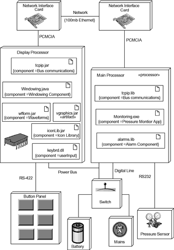
Subsystems need not be constrained to be only composed of software elements. In systems engineering environments, it is common to use the UML notion of subsystem to represent things that are internally decomposed into parts of various kinds, including software, electronic, mechanical and chemical. 2.4.5 Deployments: Nodes and NonesuchAs mentioned earlier, artifacts such as files implement software elements such as components, subsystems, and classes. Artifacts are useful for describing processes, and the UML can be used to model development processes and document flow, but primarily we'll be concerned here about artifacts that deploy executable software elements. While we don't normally think of executing documents, we do think of executing .exe, .dll, and .lib files, and we think of these artifacts as being the implementation of components and other objects. In the UML, the thing onto which an artifact is deployed is called a node. A node executes the implementation of these software elements. So it is with UML 2.0. While in UML 1.x, it was common to nest a component within a node, in UML 2.0, we nest artifacts that implement them instead. In UML 2.0, the two primary kinds of nodes are devices and execution environments. Devices are commonly further stereotyped into «processors» and «simple devices», a «processor» being a device that executes the software that you write, while a «simple device» is one that does not (such as a printer, display, keyboard, or sensor). It is very common to use iconic stereotypes for various kinds of «simple devices» such as DC motors, stepper motors, IR sensors, thermometers, force sensors, pressure transducers, and so on. The other kind of node, an execution environment, is a kind of virtualized device, such as the Java Virtual Machine. Nodes connect to other nodes via connections, which represent the physical media through which the artifacts executing on the nodes send and receive messages. As with UML 1.x, a node is the only three-dimensional icon used, and artifacts may optionally be shown on them. While perhaps not strictly proper, it is still nevertheless perfectly reasonable to nest components in the nodes as well with the understanding that we are, in fact, executing the implementing artifact on the node. Figure 2-17 shows a typical deployment diagram. The three-dimensional boxes are nodes you can see that both textual stereotypes are used as well as icons, so you may use whichever you prefer. Several kinds of connections are shown, including Ethernet, RS485, RS232, and a digital line of exchanging messages and control information as well as a power bus. The artifacts inside the nodes may be indicated with the textual stereotype «artifact», or they may be shown with the more common artifact stereotype icon (a rectangle with a folded corner). These artifacts implement components which may also be shown within a constraint, as is done for a number of the artifacts. The artifacts shown are java files, .jar Java repositories, dynamic link libraries, and executable .exe files. Figure 2-17. Nodes and Deployments
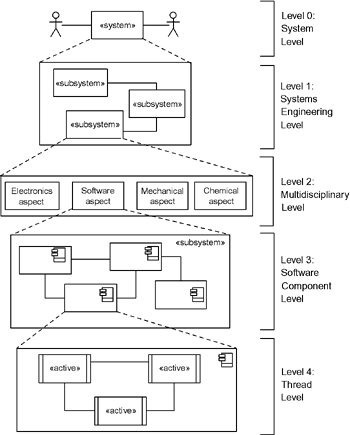
2.4.6 So, Nodes or Classes?A node is a kind of structured class in the UML 2.0, so it has all the richness of classes it may have behavior and state machines. This is important in systems engineering when these software and hardware elements must be executed, simulated, and/or analyzed for performance. This work can be done by representing all the elements both hardware and software as classes and then generating VHDL or SystemC for the ones that are realized in hardware and C, C++, or Ada for the ones that are realized in software. It is most likely more work to manually change nodes to classes and vice versa within design tools, so when different hardware/software breakdowns are to be evaluated, it probably is less work to just model everything as classes. Note that this applies for systems engineering (rather than software engineering) work primarily. If your project uses COTS (commercial off-the-shelf) hardware or the hardware is not being codesigned, the decomposition of the system can be made more obvious by making the hardware pieces nodes and the software pieces classes. However, it really can be done either way. 2.4.7 Architectural HierarchyWhile the concepts of system, subsystem, and component are sufficiently flexible to support most any runtime organizational schema you would like to employ, I generally find it useful to use these concepts in a particular way. The system (shown with the «system» class stereotype) represents the entire system under development. The largest scale pieces of the system are «subsystem» objects (which, in systems engineering environments may contain hardware and software elements). Subsystems may in turn contain software (and other kinds of) components. Components may contain multiple threads, modeled with «active» objects. And the passive or semantic objects, which do the real work of the system, run within the «active» objects. For really large projects, you may have all of these levels and perhaps even multiples at one or more levels for example, a large system might have subsystems decomposed into subsubsystems before you get to the component level. For simpler systems, you may not require all of these levels you might skip the subsystem level and just have components. You may even find that, for very simple systems, you only need the system, «active» objects, and semantic objects. Your mileage may vary in terms of how you apply these concepts, but I have found this a useful way to use the organizational concepts in practice. This size hierarchy is shown in Figure 2-18. Figure 2-18. Levels of Abstraction in Architecture
This set of levels is a recommendation only and is not mandated (or even discussed) in the UML specification. In my experience, using the UML concepts in this way maps well to engineers' expectations. |
EAN: 2147483647
Pages: 127
