Parts of a Computer System
A practical computer system consists of hardware and software. The major hardware components of a typical microcomputer system are a central processing unit (CPU), memory circuits, a keyboard for input, a monitor or some other display device, specialized input/output devices like a mouse, a modem, or a sound card, and one or more disk drives to store programs and data. Software refers to the programs that the hardware executes, including system software and application software.
These basic components vary from one computer system to another. This chapter discusses how the memory and CPU look to the assembly language programmer for a particular class of microcomputers, the IBM PC and compatible systems. These computers have an Intel 80×86 CPU; that is, an 8086 or 8088, an 80286, an 80386, an 80486, or a Pentium processor.[1] This book assumes a system that has an 80386 or higher processor and a 32-bit operating system such as Windows 95 or Windows NT. The remainder of the book is concerned with using assembly language to program these systems, with the intent of showing how such systems work at the hardware level.
PC Hardware Memory
The memory in an IBM PC or compatible microcomputer is logically a collection of "slots," each of which can store one byte of instructions or data. Each memory byte has a 32-bit numeric label called its physical address. A physical address can always be expressed as eight hex digits. The first address is 0000000016 and the last address can be as large as the unsigned number FFFFFFFF16. Figure 2.1 shows a logical picture of the possible memory in a PC. Since FFFFFFFF16 = 4,294,967,295, a PC can contain up to 4,294,967,296 bytes of memory, or four gigabytes. In practice, the user memory in most PCs is smaller than this.
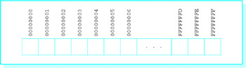
Figure 2.1: Logical picture of PC memory
Prior to the 80386 chip, the Intel 80×86 family of processors could only directly address 220 bytes of memory. They used 20-bit physical addresses, often expressed as 5-hex-digit addresses ranging from 00000 to FFFFF.
Physically a PC's memory consists of integrated circuits (ICs). Many of these chips provide random access memory (RAM), which can be written to or read from by program instructions. The contents of RAM chips are lost when the computer's power is turned off. Other ICs are read-only memory (ROM) chips, which permanently retain their contents and can be read from but not written to.
The assembly language programs in this book will use a flat memory model. This means that the programs will actually encode 32-bit addresses to logically reference locations in a single memory space where data and instructions are stored.
The Intel 80×86 architecture also provides for a segmented memory model. In the original 8086/8088 CPU, this memory model was the only one available. With the 8086/8088, the PC's memory is visualized as a collection of segments, each segment 64 Kbytes long, starting on an address that is a multiple of 16. This means that one segment starts at address 00000, another (overlapping the first) starts at address 16 (0001016), another starts at address 32 (0002016), etc. Notice that the starting address of a segment ends in 0 when written in hex. The segment number of a segment consists of the first four hex digits of its physical address.
A program written for the 8086/8088 does not encode a five-hex-digit address. Instead, each memory reference depends on its segment number and a 16-bit offset from the beginning of the segment. Normally only the offset is encoded, and the segment number is deduced from context. The offset is the distance from the first byte of the segment to the byte being addressed. In hex, an offset is between 0000 and FFFF16. The notation for a segment-offset address is the four-hex-digit segment number followed by a colon (:) followed by the four-hex-digit offset.
As an example, 18A3:5B27 refers to the byte that is 5B27 bytes from the beginning of the segment starting at address 18A30. Add the starting address and the offset to get the five-hex-digit address.
 18A30 starting address of segment 18A3
 +  5B27 offset
 1E557 five-hex-digit address
From the 80386 on, 80×86 processors have had both 16-bit and 32-bit segmented memory models available. Segment numbers are still 16-bits long, but they do not directly reference a segment in memory. Instead, a segment number is used as an index into a table that contains the actual 32-bit starting address of the segment. In the 32-bit segmented model, a 32-bit offset is added to that starting address to compute the actual address of the memory operand. Segments can be logically useful to a programmer: In the segmented Intel model, the programmer normally assigns different memory segments to code, data, and a system stack. The 80×86 flat memory model is really a 32-bit segmented model with all segment registers containing the same value.
In reality, the 32-bit address generated by a program is not necessarily the physical address at which an operand is stored as the program executes. There is an additional layer of memory management performed by the operating system and the Intel 80×86 CPU. A paging mechanism is used to map the program's 32-bit addresses into physical addresses. Paging is useful when a logical address generated by a program exceeds the physical memory actually installed in a computer. It can also be used to swap parts of a program from disk as needed when the program is too large to fit into physical memory. The paging mechanism will be transparent to us as we program in assembly language.
Exercises 2.1
- Suppose that you buy a PC with 32 MBytes of RAM. What is the 8-hex-digit address of the "last" byte?
- Suppose that you discover that RAM addresses 000C0000 to 000C7FFF are reserved for a PC's video adapter. How many bytes of memory is this?
- Suppose that you have an Intel 8086. Find the five-hex-digit address that corresponds to each of these segment:offset pairs:
(a)
2B8C:8D21
(b)
059A:7A04
(c)
1234:5678
[1]Intel produced an 80186 CPU, but it was rarely used in commercial micro computers.
PC Hardware The CPU
The original 8086/8088 CPU could execute over 200 different instructions. This instruction set has been extended as the 80×86 processor family has expanded to include the 80286, 80386, 80486, and Pentium processors. Much of this book will be concerned with using these instructions to implement programs so that you understand the machine-level computer capabilities. Other manufacturers make CPUs that execute essentially the same instruction set, so that a program written for an Intel 80×86 runs without change on such CPUs. Many other processor families execute different instruction sets. However, most have a similar architecture, so that the basic principles you learn about the 80×86 CPUs also apply to these systems.
A CPU contains registers, each an internal storage location that can be accessed much more rapidly than a location in RAM. The application registers are of most concern to the programmer. An 80×86 CPU (from 80386 on) has 16 application registers. Typical instructions transfer data between these registers and memory or perform operations on data stored in the registers or in memory. All of these registers have names, and some of them have special purposes. Their names are given below and some of their special purposes are described. You will learn more special purposes later.
The EAX, EBX, ECX, and EDX registers are called data registers or general registers. The EAX register is sometimes known as the accumulator since it is the destination for many arithmetic results. An example of an instruction using the EAX register is
add eax, 158
which adds the decimal number 158 (converted to doubleword length 2's complement form) to the number already in EAX, replacing the number originally in EAX by the sum. (Full descriptions of the add instruction and others mentioned below will appear in Chapter 4.)
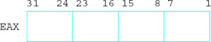
Each of EAX, EBX, ECX, and EDX is 32 bits long. The Intel convention is to number bits right to left starting with 0 for the low-order bit, so that if you view one of these registers as four bytes, then the bits are numbered like this
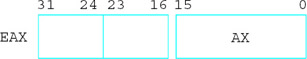
Parts of the EAX register can be addressed separately from the whole. The low-order word, bits 0-15, is known as AX.
The instruction
sub ax, 10
subtracts 10 from the word stored in AX, without changing any of the high-order bits (16-31) of EAX.
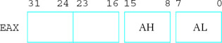
Similarly, the low-order byte (bits 0-7) and the high-order byte (bits 8-15) of AX are known as AL and AH, respectively.
The instruction
mov ah, '*'
copies 2A, the ASCII code for an asterisk, to bits 8-15, without changing any of the other bits of EAX.
The EBX, ECX, and EDX registers also have low-order words BX, CX, and DX, which are divided into high-order and low-order bytes BH and BL, CH and CL, and DH and DL. Each of these parts can be changed without altering other bits. It may be a surprise that there are no comparable names for the high-order words in EAX, EBX, ECX, and EDX-you cannot reference bits 16-31 independently by name.
The 8086 through 80286 processors had four 16-bit general registers called AX, BX, CX, and DX. The "E" was added for "extended" with the 32-bit 80386 registers. However, the 80386 and later architectures effectively include the older 16-bit architecture.
There are four additional 32-bit registers that Intel also calls general, ESI, EDI, ESP, and EBP. In fact, you can use these registers for operations like arithmetic, but normally you should save them for their special purposes. The ESI and EDI registers are index registers, where SI stands for source index and DI stands for destination index. One of their uses is to indicate memory addresses of the source and destination when strings of characters are moved from one place to another in memory. They can also be used to implement array indexes. The names SI and DI can be used for the low-order words of ESI and EDI, respectively, but we will have little occasion to do this.
The ESP register is the stack pointer for the system stack. It is rarely changed directly by a program, but is changed when data is pushed onto the stack or popped from the stack. One use for the stack is in procedure (subroutine) calls. The address of the instruction following the procedure call instruction is stored on the stack. When it is time to return, this address is retrieved from the stack. You will learn much more about the stack and the stack pointer register in Chapter 6. The name SP can be used for the low-order word of ESP, but this will not be done in this book.
The EBP register is the base pointer register. Normally the only data item accessed in the stack is the one that is at the top of the stack. However, the EBP register is often used to mark a fixed point in the stack other than the stack top, so that data near this point can be accessed. This is also used with procedure calls, particularly when parameters are involved.
There are six 16-bit segment registers: CS, DS, ES, FS, GS, and SS. In the older 16-bit segmented memory model, the CS register contains the segment number of the code segment, the area of memory where the instructions currently being executed are stored. Since a segment is 64K long, the length of a program's collection of instructions is often limited to 64K; a longer program requires that the contents of CS be changed while the program is running. Similarly DS contains the segment number of the data segment, the area of memory where most data is stored. The SS register contains the segment number of the stack segment, where the stack is maintained. The ES register contains the segment number of the extra data segment that could have multiple uses. The FS and GS registers were added with the 80386 and make possible easy access to two additional data segments.
With the flat 32-bit memory model we will use, the segment registers become essentially irrelevant to the programmer. The operating system will give each of CS, DS, ES, and SS the same value. Recall that this is a pointer to table entry that includes the actual starting address of the segment. That table also includes the size of your program, so that the operating system can indicate an error if your program accidentally or deliberately attempts to write in another area. However, all of this is transparent to the programmer who can just think in terms of 32-bit addresses.
The 32-bit instruction pointer, or EIP register, cannot be directly accessed by an assembly language programmer. The CPU has to fetch instructions to be executed from memory, and EIP keeps track of the address of the next instruction to be fetched. If this were a older, simpler computer architecture, the next instruction to be fetched would also be the next instruction to be executed. However, an 80×86 CPU actually fetches instructions to be executed later while it is still executing prior instructions, making the assumption (usually correct) that the instructions to be executed next will follow sequentially in memory. If this assumption turns out to be wrong, for example if a procedure call is executed, then the CPU throws out the instructions it has stored, sets EIP to contain the offset of the procedure, and then fetches its next instruction from the new address.
In addition to prefetching instructions, an 80×86 CPU actually starts execution of an instruction before it finishes execution of prior instructions. This use of pipelining increases effective processor speed.
The final register is called the flags register. The name EFLAGS refers to this register, but this mnemonic is not used in instructions. Some of its 32 bits are used to set some characteristic of the 80×86 processor. Other bits, called status flags, indicate the outcome of execution of an instruction. Some of the flag register's 32 bits are named, and the names we will use most frequently are given in Fig. 2.2.
|
Bit |
Mnemonic |
Usage |
|---|---|---|
|
0 |
CF |
carry flag |
|
2 |
PF |
parity flag |
|
6 |
ZF |
zero flag |
|
7 |
SF |
sign flag |
|
10 |
DF |
direction flag |
|
11 |
OF |
overflow flag |
Figure 2.2: Selected EFLAGS bits
Bit 11 is the overflow flag (OF). It is set to 0 following an addition in which no overflow occurred, and to 1 if overflow did occur. Similarly, bit 0, the carry flag (CF), indicates the absence or presence of a carry out from the sign position after an addition. Bit 7, the sign flag, contains the left bit of the result after some operations. Since the left bit is 0 for a nonnegative two's complement number and 1 for a negative number, SF indicates the sign. Bit 6, the zero flag (ZF) is set to 1 if the result of some operation is zero, and to 0 if the result is nonzero (positive or negative). Bit 2, the parity flag, is set to 1 if the number of 1 bits in a result is even and to 0 if the number of 1 bits in the result is odd. Other flags will be described later when their uses will be clearer.
As an example of how flags are set by instructions, consider again the instruction
add eax, 158
This instruction affects CF, OF, PF, SF, and ZF. Suppose that EAX contains the word FF FF FF F3 prior to execution of the instruction. Since 15810 corresponds to the word 00 00 00 9E, this instruction adds FF FF FF F3 and 00 00 00 9E, putting the sum 00 00 00 91 in the EAX register. It sets the carry flag CF to 1 since there is a carry, the overflow flag OF to 0 since there is no overflow, the sign flag SF to 0 (the leftmost bit of the sum 00 00 00 91), and the zero flag ZF to 0 since the sum is not zero. The parity flag PF is set to 0 since 0000 0000 0000 0000 0000 0000 1001 0001 contains three 1 bits, an odd number.
In summary, the 80×86 CPU executes a variety of instructions, using its 16 internal registers for operands and results of operations, and for keeping track of segment selectors and addresses. The registers are summarized in Fig. 2.3.
|
Name |
Length (bits) |
Use/comments |
|---|---|---|
|
EAX |
32 |
accumulator, general use; |
|
low-order-word AX, divided into bytes AH and AL |
||
|
EBX |
32 |
general use; |
|
low-order-word BX, divided into bytes BH and BL |
||
|
ECX |
32 |
general use; |
|
low-order-word CX, divided into bytes CH and CL |
||
|
EDX |
32 |
general use; |
|
low-order-word DX, divided into bytes DH and DL |
||
|
ESI |
32 |
source index; source address in string moves, array index |
|
EDI |
32 |
destination index; address of destination, array index |
|
ESP |
32 |
stack pointer; address of top of stack |
|
EBP |
32 |
base pointer; address of reference point in the stack |
|
CS |
16 |
holds selector for code segment |
|
DS |
16 |
holds selector for data segment |
|
ES |
16 |
holds selector for extra segment |
|
SS |
16 |
holds selector for stack segment |
|
FS |
16 |
holds selector for additional segment |
|
GS |
16 |
holds selector for additional segment |
|
EIP |
32 |
instruction pointer; address of next instruction to be |
|
fetched |
||
|
EFLAGS |
32 |
collection of flags, or status bits |
Figure 2.3: 80×86 registers
Exercises 2.2
- For each add instruction below, assume that EAX contains the given contents before the instruction is executed, and give the contents of EAX as well as the values of the CF, OF, SF, and ZF flags after the instruction is executed:
EAX before
Instruction
(a)
00 00 00 45
add eax, 45
(b)
FF FF FF 45
add eax, 45
(c)
00 00 00 45
add eax, -45
(d)
FF FF FF 45
add eax, -45
(e)
FF FF FF FF
add eax, 1
(f)
7F FF FF FF
add eax, 100
- In an 8086 program, suppose that the data segment register DS contains the segment number 23D1 and that an instruction fetches a word at offset 7B86 in the data segment. What is the five-hex-digit address of the word that is fetched?
- In an 8086 program, suppose that the code segment register CS contains the segment number 014C and that the instruction pointer IP contains 15FE. What is the five-hex-digit address of the next instruction to be fetched?
PC Hardware Input Output Devices
A CPU and memory make a computer, but without input devices to get data or output devices to display or write data, the computer is not usable for many purposes. Typical input/output (I/O) devices include a keyboard or a mouse for input, a monitor to display output, and a disk drive for data and program storage.
An assembly language programmer has multiple ways to look at I/O devices. At the lowest level, each device uses a collection of addresses or ports in the I/O address space. The 80×86 architecture has 64K port addresses, and a typical I/O device uses three to eight ports. These addresses are distinct from ordinary memory addresses. The programmer uses instructions that output data or commands to these ports or that input data or status information from them. Such programming is very tedious and the resulting programs are difficult to reuse with different computer systems.
Instead of using separate port addresses, a computer system can be designed to use addresses in the regular memory address space for I/O device access. Such a design is said to use memory-mapped input/output. Although memory-mapped I/O is possible with the 80×86, it is not used with most PCs.
Because of the difficulty of low-level programming of I/O devices, a common approach is to use procedures that do the busywork of communicating with the devices, while allowing the programmer a higher-level, more logical view of the devices. Many such routines are still fairly low-level; examples are procedures to display a single character on the CRT or get a single character from the keyboard. A higher-level procedure might print a string of characters on a printer.
An assembly language programmer may write input/output procedures, using knowledge of input/output ports and devices. Some computers have input/output procedures built into ROM. Many operating systems (see Section 2.4) also provide input/output procedures.
Exercises 2.3
The previous discussion states that there are 64K port addresses.
- How many addresses is this (in decimal)?
- Assuming that the first address is 0, what is the last address?
- Express the range of port addresses in hex.
PC Software
Without software, computer hardware is virtually useless. Software refers to the programs or procedures executed by the hardware. This section discusses different types of software.
PC Software The Operating System
A general-purpose computer system needs an operating system to enable it to run other programs. The original IBM PC usually ran the operating system known as PC-DOS; compatible systems used the very similar operating systems called MS-DOS. DOS stands for disk operating system. All of these operating systems were developed by Microsoft Corporation; PC-DOS was customized by IBM to work on the IBM PC, and the versions of MS-DOS that ran on other computer systems were sometimes customized by their hardware manufacturers. Later versions of PC-DOS were produced solely by IBM.
The DOS operating systems provide the user a command line interface. DOS displays a prompt (such as C:>) and waits for the user to type a command. When the user presses the Enter (or Return) key, DOS interprets the command. The command may be to perform a function that DOS knows how to do (such as displaying the directory of file names on a disk), or it may be the name of a program to be loaded and executed.
Many users prefer a graphical user interface that displays icons representing tasks or files, so that the user can make a selection by clicking on an icon with a mouse. Microsoft Windows provided a graphical user interface for PCs. The versions through Windows 3.1 enhanced the operating environment, but still required DOS to run. Windows 95 included a major revision of the operating system, which was no longer sold separately from the graphical user interface. In Windows 95 the graphical user interface became the primary user interface, although a command line interface was still available.
PC Software Text Editors
A text editor is a program that allows the user to create or modify text files that are stored on disk. A text file is a collection of ASCII codes. The text files of most interest in this book will be assembly language source code files, files that contain assembly language statements. An editor is sometimes useful to prepare a data file as well.
Later versions of MS-DOS and Windows 95 provide a text editor called Edit. Edit is invoked from the command line prompt. This full-screen editor uses all or part of the monitor display as a window into the file. The user can move the window up or down (or left or right) to display different portions of the file. To make changes to the file, cursor control keys or the mouse are used to move the cursor to the place to be modified, and the changes are entered.
Microsoft Windows includes a text editor called Notepad. It is also a full-screen editor. Either Edit or Notepad work well for writing assembly language source programs.
Word processors are text editors that provide extra services for formatting and printing documents. For example, when one uses a text editor, usually the Enter key must be pressed at the end of each line. However, a word processor usually wraps words automatically to the next line as they are typed, so that Enter or some other key is used only at the end of a paragraph. The word processor takes care of putting the words on each line within specified margins. A word processor can sometimes be used as an editor to prepare an assembly language source code file, but some word processors store formatting information with the file along with the ASCII codes for the text. Such extra information may make the file unsuitable as an assembly language source code file, so it is safest to avoid a word processor when creating an assembly language source program.
PC Software Language Translators and the Linker
Language translators are programs that translate a programmer's source code into a form that can be executed by the computer. These are usually not provided with an operating system. Language translators can be classified as interpreters, compilers, or assemblers.
Interpreters directly decipher a source program. To execute a program, an interpreter looks at a line of source code and follows the instructions of that line. Basic or Lisp language programs are often executed by an interpreter. Although the interpreter itself may be a very efficient program, interpreted programs sometimes execute relatively slowly. An interpreter is generally convenient since it allows a program to be quickly changed and run. The interpreter itself is often a very large program.
Compilers start with source code and produce object code that consists mostly of instructions to be executed by the intended CPU. High-level languages such as Pascal, Fortran, Cobol, C, and C++ are commonly compiled. The object code produced by a compiler must often be linked or combined with other object code to make a program that can be loaded and executed. This requires a utility called a linker, usually provided with a compiler.
A debugger allows a programmer to control execution of a program, pausing after each instruction or at a preset breakpoint. When the program is paused, the programmer can examine the contents of variables in a high-level language or registers or memory in assembly language. A debugger is useful both to find errors and to "see inside" a computer to find out how it executes programs.
Integrated development environments use a single interface to access an editor, a compiler, and a linker. They also initiate execution of the program being developed and frequently provide other utilities, such as a debugger. An integrated development environment is convenient, but may not always be available for a particular programming language.
An assembler is used much like a compiler, but translates assembly language rather than a high-level language into machine code. The resulting files must normally be linked to prepare them for execution. Because assembly language is closer to machine code than a high-level language, the job of an assembler is somewhat simpler than the job of a compiler. Assemblers historically existed before compilers.
Using again the assembly language instruction cited in Section 2.2,
add eax, 158
is translated by the assembler into the five bytes 05 00 00 00 9E. The first byte 05 is the op code (operation code), which says to add the number contained in the next four bytes to the doubleword already in the EAX register. The doubleword 00 00 00 9E is the 2's complement representation of 15810.
Summary
This chapter has discussed the hardware and software components that make up a PC microcomputer system.
The major hardware components are the CPU and memory. The CPU executes instructions and uses its internal registers for instruction operands and results and to determine addresses of data and instructions stored in memory. Objects in memory can be addressed by 32-bit addresses. In a flat memory model, such addresses are effectively actual addresses. In a segmented memory model, addresses are calculated from a starting address determined from a segment number and an offset within the segment.
Input/output at the hardware level uses a separate collection of addresses called ports. Input/output is often done through operating systems utilities.
An operating system is a vital software component. Through a command line or a graphical user interface, it interprets the user's requests to carry out commands or to load and execute programs.
A text editor, an assembler, and a linker are necessary software tools for the assembly language programmer. These may be separate programs or available as part of an integrated development environment. A debugger is also a useful programmer's tool.
Preface
- Representing Data in a Computer
- Parts of a Computer System
- Elements of Assembly Language
- Basic Instructions
- Branching and Looping
- Procedures
- String Operations
- Bit Manipulation
- The Assembly Process
- Floating-Point Arithmetic
- Decimal Arithmetic
- Input/Output
- Appendix A Hexadecimal/ASCII conversion
- Appendix B Useful MS-DOS Commands
- Appendix C MASM 6.11 Reserved Words
- Appendix D 80x86 Instructions (by Mnemonic)
- Appendix E 80x86 Instructions (by Opcode)
EAN: 2147483647
Pages: 113
