Flylib.com

Books Software


Implementing B-Spline Code

 
progress indicator progress indicator progress indicator progress indicator

Moving Beyond Fluttering Sheets

So far, all of the surface examples have taken the form of sheets that are stretched and deformed as the control points change. This is an easy way to demonstrate the basics; not all that many game objects can be represented as rubber sheets. As a more real-world example, I have created the shape of a space ship, as shown in Figure 9.4.


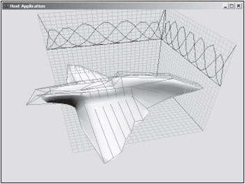
Figure 9.4: NURBS space ship.

The model is not complete (there is no bottom), but it still demonstrates all of the important points. First, it's important to note that the code is exactly the same as described earlier. The only things that have changed are the positions of the control points. The code can be found on the CD under Code\Chapter09 - NURBS Patch Model, and you can find the control point positions in the FillPatchBuffer function.

Notice that the model is no longer a wavy square shape. This is because the control points are no longer arranged in a square shape. Instead, the control points along the edge are shaped into the rough outline of the ship. Figures 9.5 and 9.6 demonstrate this. First, I started with a nonuniform grid of control points. This will allow me to put more detail and control in certain areas than in others.


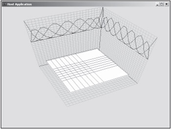
Figure 9.5: Basic NURBS patch with nonuniform control grid.


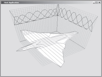
Figure 9.6: Basic space ship shape.

Next, the control points are moved to create the rough shape of the ship. I have disabled the height changes in this screenshot in order to emphasize the irregular shape.

Finally, the control point heights are changed to complete the ship. Figure 9.7 is basically the same shot as Figure 9.4, only now the model is drawn in wireframe so that you can see how the mesh is laid out.


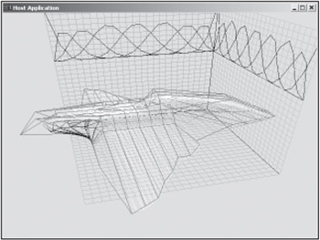
Figure 9.7: Final ship in wireframe.

The final object is much closer to something you'd actually use in a game. In a real-world situation, you probably wouldn't want to model the shape by hardcoding control point positions. Instead, you might want to create your own NURBS model format or use a NURBS modeler such as Rhino. However you choose to create the model, the NURBS representation does have some advantages.

progress indicator progress indicator progress indicator progress indicator
text only
 
progress indicator progress indicator progress indicator progress indicator

Advantages of NURBS Surfaces

One of the advantages of a NURBS model over a traditional polygonal model is that mathematical formats are inherently more compact. For instance, you can model a circle as a set of N vertices, or you can model it as a center position and radius. The latter representation is much better if you want to send the model over a network or create various levels of detail.

A NURBS model is conceptually the same as the circle example. Figure 9.5 shows that 81 control points were used to generate the space ship model. In Figure 9.4, the model was rendered with 400 vertices. Including knot and weight vectors, the NURBS representation would still require roughly 75% less bandwidth to send over the network.

With the advent of DVDs and broadband, one could argue that band -width considerations are not as critical as they once were. That might or might not be true, but there is another advantage to NURBS. A mathematical representation is not tied to any one level of detail. This means that several equivalent models can be generated from the same control grid. Figure 9.8 shows three examples of the ship at different levels of detail. At the higher levels of detail, note the differences in the tail and where the wing meets the fuselage.


Figure 9.8: Ships for yesterday , today, and tomorrow.

There are two points to be made here. The first is that now the same 81 control points can be used to represent many more vertices across more than one instantiation of the model. The other point is that one can imagine a system that tunes the model based on the end user 's configuration. You can begin to imagine scenarios where the users upgrade their machine and your game not only runs faster, but the models actually "upgrade" themselves to be smoother. The control grid is far more compact and flexible than including a large number of models on your DVD. Remember, the three models in Figure 9.8 are all based on the same NURBS representation.

One could argue that the same advantages could be achieved with subdivision surfaces and/or some of the hardware-based subdivision features. That might be true in some instances, but it might still be worthwhile to generate your own scalable meshes. In some instances, hardware subdivision is inappropriate because you need to know where the vertices are for computations such as collision detection or shadow generation.

There may also be occasions where you might want to use different levels of detail for different tasks . For example, you might generate a low-res model for collision detection, but a very high-res model for rendering. The results of the collision detection calculations could drive deformations of the control mesh that could then propagate to the high-res model.

It's an exciting time in computer graphics and there are many tools available to you. Different circumstances call for different solutions. It's important to understand the advantages of each solution and use whichever one makes the most sense.

progress indicator progress indicator progress indicator progress indicator