Intrusion Prevention Service
| Cisco ASA supports an inline Intrusion Prevention Security Service on the Advanced Inspection and Protection Security Services Module (AIP-SSM). The Intrusion Prevention module provides the ability to identify and drop the IP packets of an active network attack. The actual configuration of the IPS signatures is not shown in the base ASA configuration file, which can be displayed with telnet/SSH or ASDM. The existence of an AIPSSM module is indicated in the show module telnet/SSH CLI command as shown in Example 3-1. Example 3-1. The show module Command
The process to configure IPS inspection of network traffic with the AIP-SSM with ASDM includes the following:
Launch ASDM for IPS ConfigurationIPS Configuration is simple and intuitive with ASDM. You initiate IPS Configuration by selecting Configuration from the top panel and IPS from the left panel. The AIP-SSM module can be separately managed from the ASA chassis and has its own IP address. In addition to ASDM, you can also manage the AIP module by telnet/SSH directly to the IP address of the IPS module. You can also centrally manage the ASA AIP-SSM with the Cisco Security Manager. Cisco Security Manager is Cisco's centralized security manager that you can use to manage or configure security components on ASA, IPS, and router devices. Cisco Security Manager is a very strategic element in the Cisco security portfolio. Cisco Security Manager is discussed in detail in Chapter 9, "Cisco Security Manager." You can display or view the CLI file of the AIP-SSM, which can be created with ASDM, by issuing the session module slot command from the base ASA platform. ASDM will indicate the IP address of the AIP-SSM automatically after you select Configure and IPS from the main ASDM homepage. The AIP-SSM module also supports a separate username and password. Figure 3-3 shows an example of how to access the GUI display of the AIPSSM module configuration from ASDM. Figure 3-3. Connecting to IPS Configuration in ASDM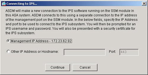 Configure Service Policy RulesASA also provides the ability to specify which subset of network traffic will be sent from the ASA chassis to the AIP-SSM module for IPS inspection. The definition of network traffic to send to the AIP-SSM module is configured under the Service Policy Rules section as shown in Figure 3-4. Figure 3-4. Service Policy Rules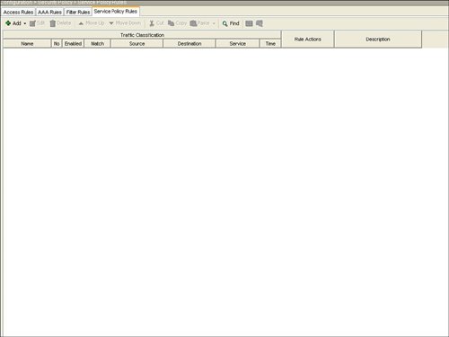 The steps to configure a specific traffic flow in a service policy rule include the following:
The next step, as indicated in Figure 3-5, is configuration of the individual interface or global list of interfaces for the service policy rule. There can be only one service policy rule that is applied to an interface. Figure 3-5. Interface for Service Policy Rule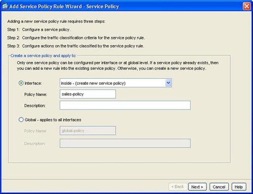 Next, configure the traffic class name and network traffic to be matched in the service policy rule. Figure 3-6 shows the Traffic Classification Class window. Figure 3-6. Create Traffic Class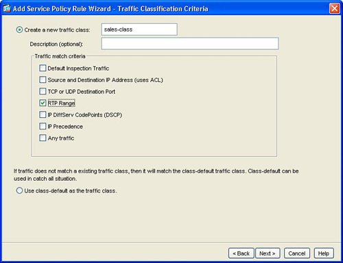 This example created a new traffic class in order to process or match network traffic for Real-Time Protocol (RTP) packets. RTP is used for voice and multimedia network traffic. Figure 3-7 displays how to define the RTP port range of 4000 to 5000 in the new traffic class for the interface. Figure 3-7. Define Network Traffic for Traffic Class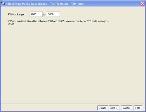 Figure 3-8 defines how to configure IPS inspection for this traffic flow. Configuring IPS prevention for this traffic flow in the service policy rule sends the matched traffic class from the ASA chassis to the AIP-SSM module for IPS inspection. This example defines IPS to be inline. Inline IPS means that this traffic can be dropped for a match of an IPS signature for packets that match the network traffic class. This example also defines IPS to fail-open, which means that, in the event of a failure of the AIP-SSM module, this traffic class for the specified interface will not be dropped and will continue to flow through the ASA. Figure 3-8. Enable IPS for Traffic Flow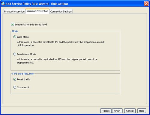 Figure 3-9 displays the resulting service policy rule in the service policy table for the new traffic class to send RTP packets from the inside interface to the AIP-SSM module for inline IPS inspection. Figure 3-9. Service Policy Rule Table Entry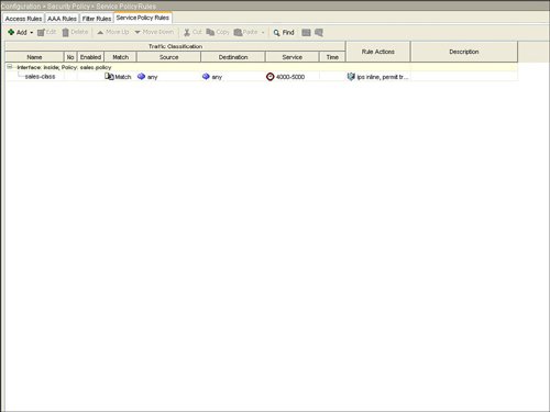 Example 3-2 displays the resulting class-map, policy-map, and service-policy CLI commands on the base ASA platform. Example 3-2. CLI for Service Policy Rule
Define IPS SignaturesAfter configuring any specific service policy rules, you next configure the specific IPS signatures that will be used to inspect the network traffic for a potential network attack. IPS can be inline, which means that the ASA product deals with the real network packet of a possible attack in real time, as opposed to a copy of the network traffic from a span port on a Catalyst LAN switch as typically implemented with an intrusion detection system (IDS) solution. IPS signature configuration is initiated by selecting the Signature Configuration option in ASDM as shown in Figure 3-10. Figure 3-10. IPS Signature Configuration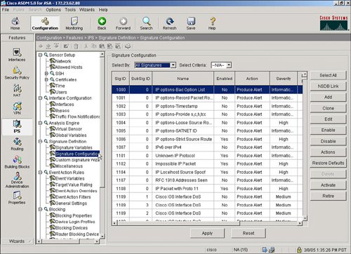 IPS signatures are divided into several subcategories, including Layer 2/Layer 3/Layer 4 (L2/L3/L4) protocol, attack, and operating system (OS) platforms. Target OS platform signatures include Linux, Windows, MacOS, Netware, and Cisco IOS. Figure 3-11 displays the signatures subcategories. Figure 3-11. IPS Signature Subcategories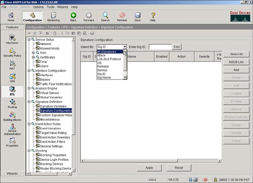 The attack signatures are composed of several attack subcategories including adware/ spyware, distributed denial of service (DDoS), DoS, and file access. Figure 3-12 shows an example of these attack subcategories. Figure 3-12. Attack Signature Subcategories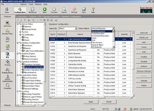 Let's say that a user wants to deploy the attack signatures to detect spyware. The process to deploy the attack signature is as simple as selecting the spyware category, highlighting the spyware signature, and then selecting the Enable and Apply buttons. The location in ASDM to select a spyware signature and to select the Enable and Apply buttons in ASDM is shown in Figure 3-13. Figure 3-13. Applying Spyware Detection Signatures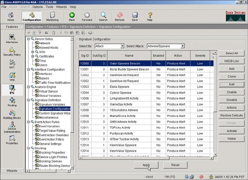 |
EAN: 2147483647
Pages: 112