Subclassing the Lathe Shape
The Lathe ShapeA LatheShape3D object first creates a lathe curve using the points supplied by the user and then decorates it with color or a texture. The choice between color and texture is represented by two constructors: public LatheShape3D(double xsIn[], double ysIn[], Texture tex) { LatheCurve lc = new LatheCurve(xsIn, ysIn); buildShape(lc.getXs( ), lc.getYs( ), lc.getHeight( ), tex); } public LatheShape3D(double xsIn[], double ysIn[], Color3f darkCol, Color3f lightCol) // two colors required: a dark and normal version of the color { LatheCurve lc = new LatheCurve(xsIn, ysIn); buildShape(lc.getXs( ), lc.getYs( ), lc.getHeight( ), darkCol, lightCol); }Both versions of buildShape( ) call createGeometry( ) to build a QuadArray for the shape. Then the four-argument version of buildShape( ) lays down a texture, and the five-argument version calls createAppearance( ) to add color. Creating the GeometrycreateGeometry( ) passes the lathe curve coordinates to surfaceRevolve( ), which returns the coordinates of the resulting shape. The coordinates are used to initialize a QuadArray, complete with normals (to reflect light) and texture coordinates if a texture is going to be wrapped around the shape: private void createGeometry(double[] xs, double[] ys, boolean usingTexture) { double verts[] = surfaceRevolve(xs, ys); // use GeometryInfo to compute normals GeometryInfo geom = new GeometryInfo(GeometryInfo.QUAD_ARRAY); geom.setCoordinates(verts); if (usingTexture) { geom.setTextureCoordinateParams(1, 2); // set up tex coords TexCoord2f[] texCoords = initTexCoords(verts); correctTexCoords(texCoords); geom.setTextureCoordinates(0, texCoords); } NormalGenerator norms = new NormalGenerator( ); norms.generateNormals(geom); setGeometry( geom.getGeometryArray( ) ); // back to geo array }The calculation of the normals is carried out by a NormalGenerator object, which requires that the coordinates be stored in a GeometryInfo object. setTextureCoordinatesParams( ) specifies how many texture coordinate sets will be used with the geometry and specifies their dimensionality (Java 3D offers 2D, 3D, and 4D texture coordinates). The actual texture coordinates are calculated by initTexCoords( ) and added to the geometry with setTextureCoordinates( ).
You Say You Want a RevolutionsurfaceRevolve( ) generates the shape's coordinates by revolving the lathe curve clockwise around the y-axis in angle increments specified by ANGLE_INCR. This results in NUM_SLICES columns of points around the y-axis: private static final double ANGLE_INCR = 15.0; // the angle turned through to create a face of the solid private static final int NUM_SLICES = (int)(360.0/ANGLE_INCR); The coordinates in adjacent slices are organized into quadrilaterals (quads). Each quad is specified by four points, with a point represented by three floats (for the x-, y-, and z-values). The points are organized in counterclockwise order so the quad's normal is facing outward. Figure 17-13 shows how two quads are defined. Each point is stored as three floats. The surfaceRevolve( ) method is shown here: private double[] surfaceRevolve(double xs[], double ys[]) { checkCoords(xs); double[] coords = new double[(NUM_SLICES) * (xs.length-1) *4*3];Figure 17-13. Quads creation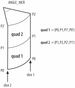 int index=0; for (int i=0; i < xs.length-1; i++) { for (int slice=0; slice < NUM_SLICES; slice++) { addCorner( coords, xs[i], ys[i],slice,index); // bottom right index += 3; addCorner( coords, xs[i+1],ys[i+1],slice,index); // top right index += 3; addCorner( coords, xs[i+1],ys[i+1],slice+1,index); //top left index += 3; addCorner( coords, xs[i],ys[i],slice+1,index); // bottom left index += 3; } } return coords; }The generated coordinates for the shape are placed in the coords[] array. surfaceRevolve( )'s outer loop iterates through the coordinates in the input arrays, which are stored in increasing order. The inner loop creates the corner points for all the quads in each slice clockwise around the y-axis. This means that the quads are built a ring at a time, starting at the bottom of the shape and working up. addCorner( ) rotates an (x, y) coordinate around to the specified slice and stores its (x, y, z) position in the coords[] array: private void addCorner(double[] coords, double xOrig, double yOrig, int slice, int index) { double angle = RADS_DEGREE * (slice*ANGLE_INCR); if (slice == NUM_SLICES) // back at start coords[index] = xOrig; else coords[index] = xCoord(xOrig, angle); // x coords[index+1] = yOrig; // y if (slice == NUM_SLICES) coords[index+2] = 0; else coords[index+2] = zCoord(xOrig, angle); // z }The x- and z-values are obtained by treating the original x-value (xOrig) as a hypotenuse at the given angle and projecting it onto the x- and z-axes (see Figure 17-14). Figure 17-14. Obtaining new x- and z-values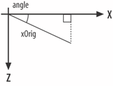 The xCoord( ) and zCoord( ) methods are simple: protected double xCoord(double radius, double angle) { return radius * Math.cos(angle); } protected double zCoord(double radius, double angle) { return radius * Math.sin(angle); }These methods carry out a mapping from Polar coordinates (radius, angle) to Cartesian ones (x, y). Since the radius argument (xOrig) never changes, the resulting coordinates will always be a fixed distance from the origin and, therefore, be laid out around a circle. These methods are protected, so it's possible to override them to vary the effect of the radius and/or angle.
Creating Texture CoordinatesIn Chapter 16, a TexCoordGeneration object mapped (s, t) values onto geometry coordinates (x, y, z). Unfortunately, the simplest TexCoordGeneration form only supports planar equations for the translation of (x, y, z) into s and t. Planar equations can produce repetitive patterns on a shape, especially shapes with flat areas. These problems can be avoided if the mapping from (x, y, z) to (s, t) is quadratic or cubic, but the design of the equation becomes harder. In those cases, it's arguably simpler to calculate s and t directly (as in this chapter) without utilizing the TexCoordGeneration class. The s value 0 is mapped to the shape's back face and increased in value around the edge of the shape in a counterclockwise direction until it reaches the back face again when it equals 1. t is given the value 0 at the base of the shape (where y equals 0) and increased to 1 until it reaches the maximum y-value. This has the effect of stretching the texture vertically. Figure 17-15 shows the s mapping applied to a circle, from a viewpoint looking down toward the XZ plane. Figure 17-15. The s mapping from above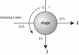 Figure 17-15 gives a hint of how to calculate s: its value at a given (x, z) coordinate can be obtained from the angle that the point makes with the z-axis. This will range between p and p (see Figure 17-16), which is converted into a value between 0 and 1. Figure 17-16. From point to angle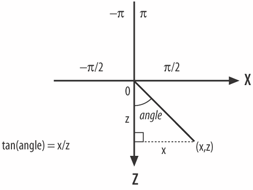 Here's the code for initTexCoords( ) that makes all this happen: private TexCoord2f[] initTexCoords(double[] verts) { int numVerts = verts.length; TexCoord2f[] tcoords = new TexCoord2f[numVerts/3]; double x, y, z; float sVal, tVal; double angle, frac; int idx = 0; for(int i=0; i < numVerts/3; i++) { x = verts[idx]; y = verts[idx+1]; z = verts[idx+2]; angle = Math.atan2(x,z); // -PI to PI frac = angle/Math.PI; // -1.0 to 1.0 sVal = (float) (0.5 + frac/2); // 0.0f to 1.0f tVal = (float) (y/height); // 0.0f to 1.0f; uses height tcoords[i] = new TexCoord2f(sVal, tVal); idx += 3; } return tcoords; }The texture coordinates are stored in an array of TexCoord2f objects, each object holding a (s, t) pair. The angles for the shape's vertices are obtained by calling Math.atan2( ), and their range of values (p to -p) is scaled and translated to (0 to 1). A Thin ProblemThe mapping described in the last subsection has a flaw, which occurs in any quad spanning the middle of the shape's back face. Figure 17-17 shows the round R example, with this problem visible as a thin R stretched down the middle of the shape's back. In short, there are two Rs, when there should only be one. The extra letter is also reversed when viewed from the back (remember that I'm placing the texture on the outside surface of the shape). Figure 17-17 should be compared with the round R example in Figure 17-8, rendered after the flaw was fixed. The same effect is apparent in all the other texture-wrapped shapes (although some shapes and textures make it harder to see). The problem is that the quads which span the middle of the back face have coordinates at angles on either side of the-z-axis. An example shows the problem in Figure 17-18. Figure 17-17. An extra R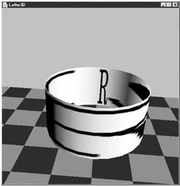 Figure 17-18. The incorrect s mapping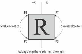 P0 and P1 have angles near to p and, therefore, s values close to 0; P0' and P1' have angles closer to p and, therefore, s values closer to 1. Consequently, the s component of the texture will be drawn in its entirety in that one quad, as seen in Figure 17-17. The solution is something of a hack. Each quad generates four TexCoord2f objects corresponding to the order of the coordinates of the quad (P0, P1, P1', P0'). In correctly textured quads, the s value for P0 is greater than P0', and P1 is greater than P1'. This is due to the surfaceRevolve( ) method rotating points clockwise around the y-axis. In incorrectly textured quads, the reverse is true: P0 is less than P0' and P1 is less than P1'. In correctTexCoords( ), every group of four TexCoord2f objects is examined for this condition, and the offending textured coordinates for P0 and P1 are adjusted to be greater than those for P0' and P1'. The code to take care of this is: private void correctTexCoords(TexCoord2f[] tcoords) { for(int i=0; i < tcoords.length; i=i+4) { if( (tcoords[i].x < tcoords[i+3].x) && (tcoords[i+1].x < tcoords[i+2].x)) { // should not increase tcoords[i].x = (1.0f + tcoords[i+3].x)/2 ; // between x & 1.0 tcoords[i+1].x = (1.0f + tcoords[i+2].x)/2 ; } } }Making an AppearanceThe createAppearance( ) method has two versions. One of them colors the shape with two colors: one for the light's ambient component and the other for diffuse illumination. This is achieved with a Material object: Appearance app = new Appearance( ): Material mat = new Material(darkCol, black, lightCol, black, 1.0f); // sets ambient, emissive, diffuse, specular, shininess mat.setLightingEnable(true); // lighting switched on app.setMaterial(mat); setAppearance(app); The other createAppearance( ) method sets the texture and uses a white Material object. The texture is combined with the color using the MODULATE mode (see Chapter 16 for more details on modulation), which allows lighting and shading effects to be blended with the texture: Appearance app = new Appearance( ); // mix the texture and the material color TextureAttributes ta = new TextureAttributes( ); ta.setTextureMode(TextureAttributes.MODULATE); app.setTextureAttributes(ta); Material mat = new Material( ); // set a default white material mat.setSpecularColor(black); // no specular color mat.setLightingEnable(true); app.setMaterial(mat); app.setTexture( tex ); setAppearance(app); |
EAN: 2147483647
Pages: 340
