Creating the Navigation Language
You now need to define the language used to describe the navigation domain. The wizard creates a sample.DSLDM file that will contain the language definition. Double-click the <YourDesignerName>.DSLDM file located in the DomainModel section of your project to open the Domain Model Designer.
You will see that a sample language is already present in this file. It was defined by the template selected during the wizard process. For the purposes of this designer, we will start from scratch, so delete all boxes from the design surface by selecting them and pressing the Delete key.
For this simple Navigation Designer, we have two concepts: a page and a site.
A page will be a number of properties such as Name and Title, and optionally holds a collection of child pages that are used to store references to other pages, enabling you to model the nested nature of navigation. We also have a parent concept called Site, and all its pages are members.
To create the concept of a Site, drag a class from the toolbox onto the design surface and change the Name property to Site, as shown in Figure 6-4.
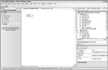
Figure 6-4
You now need to create the concept of a Page, which will be linked to the site. Drag a class from the toolbox onto the design surface and change the Name property to Page, as shown in Figure 6-5.
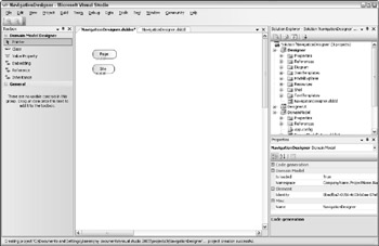
Figure 6-5
Then use an Embedding Connector from the toolbox to create the parent/child relationship between Site and Page. Draw the connector between Site and Page to create the language model depicted in Figure 6-6.
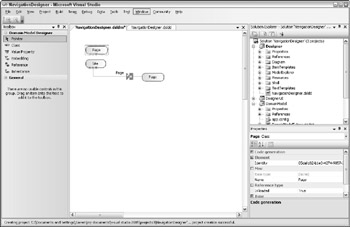
Figure 6-6
There is now a relationship between Site and Page, as you can see a new Page class has been displayed, which is connected to the Site. This is just a visual reference to the Page class that appears above. You can right-click on the new Page class and choose Bring Definition Here to make the diagram clearer, as shown in Figure 6-7.
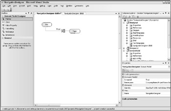
Figure 6-7
A relationship in the Domain Model Designer is represented by a line connecting two classes together. A relationship always has two symbols in the center representing roles.
The left-hand role, shown as a triangle, represents the left-hand side of the relationship. The character contained within the triangle indicates the cardinality of the relationship. In this case, * means unbounded, so a Site can have many pages. You can change this by modifying the Min and Max properties on the role.
The right-hand role, shown as a rectangle, represents the right-hand side of the relationship. Again, the character within the rectangle indicates the cardinality of the relationship — in this case, it defaults to 0 or 1, meaning a page can be a member of zero or one sites.
The domain model designer assigns default names to these roles, which in some cases are unsuitable for your domain model. Click the left triangle and change the name property to SitePages to reflect that this role represents the pages within a site. The right rectangle role is already set to Site, which is correct and reflects the Site where this page is a member.
As it stands, this language model enables you to express multiple Pages, but not the nested behavior of navigation whereby pages refer to other pages. To express this in your language, use the Reference Connector from the toolbar, and draw a connection from the Page concept back to the Page concept, effectively making it self-referencing, as per Figure 6-8.
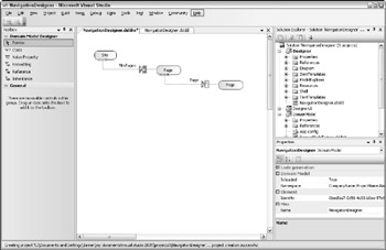
Figure 6-8
This relationship allows a Page to refer to another Page, thus enabling us to express navigation. By default, however, the left-hand side of this relationship will only allow a page to reference one other page, instead of multiple pages as we require.
The cardinality of this relationship is modeled using roles on the domain model as discussed previously. In this case, we want to modify the left-hand side of the relationship to enable us to link to many pages. Click the triangle and change the Min and Max properties to 0 to indicate unbounded, and change the name of the role to ChildPages.
The cardinality of the right-hand side of the relationship is correct, but click the rectangle and change the Name property to ReferringPages, which makes the language easier to navigate later and reflects which pages are linked to a given page. By default, this role will not generate a property linked to the Referring Page in the object model, which is required for the connector to work in the next section, so set the Is Property Generator property to true.
The relationship between the two page classes is given a default name of PageHasPage. Click the relationship and change the Name property from PageHasPage to Transition, thus making the language model clearer.
The next step for this stage is to click on the SitePages role and set the Accepts property to All. This enables the graphical designer to merge Page classes into the model at this point as they are dragged onto the surface. If you forget this step, you will be warned at compile time.
Finally, the current build of the DSL Tools requires an XML Root to be defined on the root element of your language designer for serialization purposes. Right-click the Site concept and choose Make XML Root. Your domain model should mirror the diagram shown in Figure 6-9.
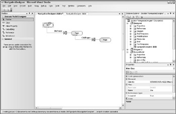
Figure 6-9
All classes on the designer inherit a Name property, which we will use to store the Page Name. For this simple designer we'll also add a Title property. You can create properties on a class by dragging the Value Property toolbox item onto the class and changing the name of the property to Title via the Name property in the properties window (see Figure 6-10).
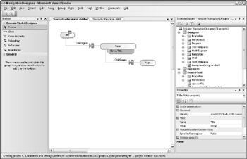
Figure 6-10
The last step for our navigation language is to add a Name property to the relationship between the Pages. Connectors don't have a name by default, but you can add one. Right-click the Transition relationship, choose Show as Class, drag a Value Property from the toolbox onto the Transition class, and call it Name, as shown in Figure 6-11.
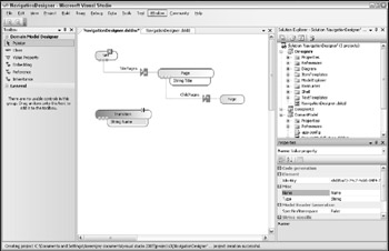
Figure 6-11
The navigation language is now complete. You can generate the object model behind this language by right-clicking on the <YourDesignerName>.dsldm.dsldmt file and choosing Run Custom Tool. A C# file is created by the DSL Tools, which produces the classes, as shown in Figure 6-12. You can see this C# file by clicking Show All Files on Solution Explorer and expanding the <YourDesignerName>.dsldm.dsldmt entry in Solution Explorer.
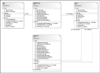
Figure 6-12
This is the object model that will be created as the user uses the diagram. New Page classes will be initialized for each Page dropped onto the diagram, and these Page classes will be added to the SitePages collection. When Pages are connected together to form the navigation, references to the pages are added to the ChildPages connection. This code is generated by the DSL Tools in the previous step, and you can use it to create an in-memory representation of your domain model. It also allows a strongly typed way to access the contents of the domain model.
The diagram in Figure 6-12 depicts the object model created for your navigation domain model. This diagram was created using the Class Diagram feature of Visual Studio 2005, which uses the same designer framework that we are using — the Class Diagram tools use a CLR Type domain model to represent classes, methods, and so on. Everything you see in this diagram, including the visual compartments that hold Fields and Methods, can be used by your custom designer.
EAN: 2147483647
Pages: 220