Application Designer Limitations and Workarounds
While Application Designer is an excellent tool for visually modeling connected service-based applications, and is one of the most promising of the new batch of visual designers to come out of Microsoft, it's not yet perfect. What it does, it does well, but there are a couple of areas in which we would like it to do more.
Modeling .NET Remoting and DCOM applications
In Chapter 1, we described the evolution of distributed computing concepts from object-oriented programming through component-based and distributed-component-based development to Web services and the service-oriented architecture.
In focusing version one of Application Designer on service-oriented designs, Microsoft did not provide a way for designers and developers working with precursor (but not yet obsolete) distributed technologies such as DCOM and .NET Remoting. You won't find prototypes for .NET Remoting applications or DCOM applications in the Application Designer toolbox.
Currently, you have three (to four) options: throw away your existing distributed design in favor of Web services (a great idea, but not practical), use the GenericApplication and GenericEndpoint prototypes to model the other distributed technologies (not ideal, but simple and useful for documentation purposes), or use the SDM SDK to model your own remoting consumer and provider endpoints (for the experts). None of these options results in support for generated code and reverse engineering. Of course, a fourth option is to maintain your unsupported (Visio) models in parallel with Application Designer.
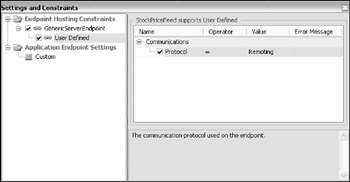
If you choose the second option—using the GenericApplication and GenericEndpoint prototypes—then you can take advantage of the features provided by the Settings and Constraints Editor, plus the Add to Toolbox functionality. For example, you could place a GenericEndpoint on an application diagram, navigate to Endpoint Hosting Constraints ![]() GenericServerEndpoint
GenericServerEndpoint ![]() User Defined, and set the communications protocol to the value Remoting, as shown in Figure 2-13.
User Defined, and set the communications protocol to the value Remoting, as shown in Figure 2-13.

Figure 2-13
You could then right-click the endpoint on your diagram and select Add to Toolbox to create a RemotingEndpoint prototype.
The situation is bound to change over time as Microsoft enables richer modeling support for distributed system design in the area of Indigo—code name for a unified programming model and runtime for building service-oriented applications with managed code, business process orchestration, and data. It's always worth checking to see whether Microsoft has made additional types available to represent other kinds of applications and endpoints before inventing your own.
Modeling Windows services and console applications
For some other application types—for example, a windows service—the situation is rather different from that just described. While Application Designer appears not to support this application type, you can, in fact, add a Windows application from the toolbox and change its Template property in the Property window to Windows Service. You won't see any difference on the diagram but the correct project type will be created when the application is implemented.
The same applies to console applications. Just change the Template property from Windows Application to Console Application.
Dynamic Modeling
One of the limitations of the Team Architect visual designers as they stand is that they do not support dynamic modeling, which in UML terms means sequence diagrams and collaboration diagrams. Though true dynamic modeling belongs for the time being in the realm of Visio, it might be useful and informative for some limited dynamic information to be indicated on our diagrams. (Note : Microsoft or third parties may provide support for dynamic modeling [e.g., sequence diagrams] via the DSL tool in the near future.)
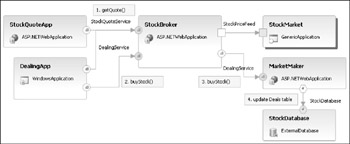
You can take advantage of the fact that a UML collaboration diagram is essentially a static diagram—like a class diagram or component diagram—by using numbered labels showing the sequence of interactions in a typical scenario. In Figure 2-14, we've used Comments (from the toolbox) as sequence labels for a "Buy Stock" scenario.

Figure 2-14
The sequence of interactions for this scenario, now reflected in the diagram, is as follows:
-
The DealingApp invokes the getQuote operation on the StockBroker StockQuoteService.
-
The DealingApp invokes the buyStock operation on the StockBroker DealingService.
-
The StockBroker delegates the request to the buyStock operation on the MarketMaker DealingService.
-
The MarketMaker updates the Deals table of StockDatabase.
For any serious dynamic modeling, such as realizing full use cases as object interactions, we recommend that you use Visio, but this technique is a feasible workaround for showing limited dynamic behavior without switching tools.
The only real restriction on our workaround is the fact that you are limited to just one application diagram per solution, so in effect you can model only one scenario at a time. To overcome that problem, you might consider this idea again when you read about the System Designer in Chapter 4, because you can have as many system diagrams as you like and you could devise a set of diagrams purely to show how applications interact in various scenarios.
In Chapter 5, you'll revisit the same technique again using class diagrams, the benefit there being the fact that you can have as many class diagrams as you like.
EAN: 2147483647
Pages: 220