Visual Designers
Visual design within Visual Studio is not new, hence the name "Visual" Studio. For some time there have been visual designers for Windows forms and web forms so that you can lay out your screen designs without resorting to code, and so that you can add behavior to buttons and other controls without having to remember how to code their event handlers. There are also other visual designers such as the XML schema designer.
The new suite of visual designers complements the existing set by providing capabilities for modeling the static aspects of your application architecture, deployment infrastructure, and lower-level object design. The complete list of new designers that we'll be introducing in this chapter and covering in-depth in this part of the book is as follows:
-
Application Designer
-
Logical Datacenter Designer
-
System Designer
-
Deployment Designer
-
Class Designer
As stated earlier, the first four comprise the Distributed System Designers (formerly called "Whitehorse") that are unique to the Visual Studio 2005 Team Edition for Software Architects. Class Designer is not unique to that edition, so you'll find it also in the Team Developer and Team Tester editions. We treat it as a member of the same set—rather than relegate it to another part of the book—because it operates in a similar fashion and contributes to the same overall visual modeling experience.
Each is covered in turn, although System Designer and Deployment Designer are covered together because they are intrinsically linked. Although you can use Application Designer and Logical Datacenter Designer individually, it makes little sense to use Deployment Designer without System Designer.
| Note | In fact, all of the designers are interrelated in very important ways via the common SDM format, as you'll see later. All we're saying here is that you can—and in fact, should—draw an Application Diagram separately from a Logical Datacenter Diagram, but it makes much less sense (arguably it's not possible) to draw a Deployment Diagram without the benefit of a set of System Definitions. |
Note that the existing designers for forms and XML schemas have a direct correspondence with the underlying code. This is true also of the new designers, which, unlike their UML equivalents, are not merely abstract representations of the underlying code.
As we introduce each of the visual designers, keep in mind that we're doing just that—introducing them. Our aim is to provide only a preview of each of the diagram types, and to place those diagrams relative to one another in the Software Development Lifecycle (SDLC). As it happens, the diagrams that we use in the following preview are all taken from the StockBroker case study that runs through the subsequent chapters, but we're not setting out to explain the details of that running example in this chapter. You'll be introduced to it more formally at the end, as a road map for the chapters that follow.
Application Designer
Application Designer enables you to define the major applications (like components in UML), their endpoints (like interfaces in UML), and their interconnections. An example application diagram based on the StockBroker case study that we'll introduce later is given in Figure 1-3.
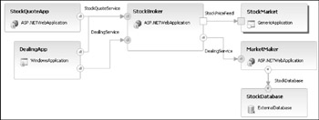
Figure 1-3
You can populate such diagrams by dragging application prototypes from the toolbox onto the diagram. These prototypes, rendered as stylized box shapes, represent ASP .NET web applications, Web services, Windows applications, and other application types. Once placed, the applications are adorned with consumer and supplier endpoints between which connections may be made.
You are allowed only one Application Diagram per solution, because ultimately it defines how your solution is composed of projects. If you implement this diagram (discussed in Chapter 2), you end up with a separate project for each application shown on the diagram, except for the MarketMaker and StockDatabase applications, which cannot be implemented.
| Note | In Chapter 2, you'll see how some applications may be implemented in a solution, whereas some—such as generic applications, external Web services, and databases—may not. |
It's no accident that we discussed service-oriented architecture (SOA) immediately before we introduced this designer, because it is biased very much toward designing service-oriented applications. While you'll find good support for adorning applications with Web service endpoints, you'll find no out-of-the-box support for adding .NET Remoting endpoints or COM endpoints as alternative communication mechanisms.
Logical Datacenter Designer
Logical Datacenter Designer enables you to define one or more deployment architectures in terms of communication boundaries, logical servers, and the protocols that interconnect them (see Figure 1-4 for an example taken from our StockBroker case study).
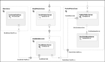
Figure 1-4
You populate such diagrams by dragging zone and server prototypes from the toolbox onto the diagram. Zones are rendered as dashed boxes representing protected network regions, and logical servers are rendered as stylized boxes representing deployment hosts. Zones and servers may be adorned with endpoints between which connections may be made.
Note that that this designer is used for logical infrastructure modeling, not physical infrastructure modeling. The five servers shown in the diagram could be hosted on five separate machines, across four machines—one in each zone—or even all on one machine, perhaps running in Virtual PCs.
You can have as many logical datacenter diagrams as you like, and the diagrams may be moved freely between solutions.
System Designer and Deployment Designer
We cover System Designer and Deployment Designer together because it makes little sense to show you one without the other. In fact, even in the simplest case of defining a default deployment scenario straight from an application diagram (as you'll see in Chapter 2), a system is created implicitly.
The two design diagrams described so far provide two alternate views of the overall architecture. The application diagram represents a solution-scoped view of the applications that you have designed, and the logical datacenter diagram represents the operations analyst's view of the logical infrastructure on which the system will be deployed. A deployment diagram depicts a deployment of the applications in a system to the logical servers in a logical datacenter. In essence, the System Designer and Deployment Designer serve to tie the two views together.
By default, each application from the application diagram binds onto an individual deployable system, but using System Designer it is possible to specify an alternative binding—for example, two applications can be combined into a single deployable system. Figure 1-5 shows such a system, along with the System View window from which you can select the applications for each system.
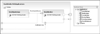
Figure 1-5
At first glance, the design surface of Deployment Designer (see Figure 1-6) looks very much the same as Logical Datacenter Designer. Look closer, however, and you'll see that each of the servers has one or more applications (also taken from the System View) bound onto it.
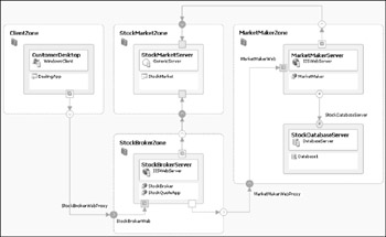
Figure 1-6
Class Designer
If you mention visual modeling to most software developers, the first thing that will spring into their minds is the UML class diagram that shows how object classes are connected together in a persistent sense or to allow navigation between them. Visual Studio 2005 provides a Class Designer most closely resembling its UML namesake.
| Note | Class Designer is not limited to the Visual Studio 2005 Team Edition for Software Architects. You can do class modeling in the Team Developer and Team Tester editions too. |
Figure 1-7 provides an example Class Designer class diagram showing classes (with fields and methods), interfaces (shown as lollipops), associations, and inheritance.
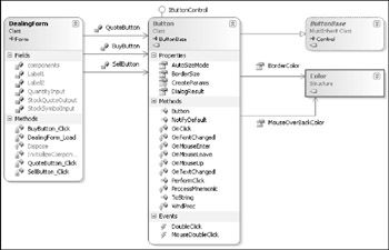
Figure 1-7
Code synchronization
Historically, visual design tools such as Rational Rose were distinct tools, separate from the development tools used for coding. Integration was achieved via a code-generation facility that would produce a one-shot cut of skeleton code as source files that could be loaded up in the IDE. Conversely, existing source files and compiled class libraries could be reverse-engineered into the design tool to document existing code using UML notation.
Some tools—including Rose but excluding Visio EA—provided a degree of round-trip engineering whereby code could be generated from the model in the design tool, modified in the IDE, reverse-engineered back into the model, and so on, ad infinitum. This round-trip engineering was not always as effective as the tool vendor claimed for the following reasons:
-
It was not always possible for the tool to reconcile every change made outside of the tool. For example, a class renamed in code is indistinguishable—as far as the tool is concerned—from a class being deleted and a new one being created.
-
Synchronization issues could arise in team scenarios, such as multiple designers and developers modifying portions of the model and the code in incompatible ways, resulting in an intractable merge.
A new precedent was set by IBM-Rational XDE, which keeps the two views—model and code—perfectly synchronized with no need to explicitly generate code or reverse engineer. Any changes you make in code are automatically reflected in the model, and vice-versa.
That is the approach taken by Class Designer, which means you won't find any feature labeled "generate code" or "reverse engineer." They're simply not needed. We'll discuss this further in Chapter 5, but for now the main implications of this are as follows:
-
Unlike UML, which can be rather generic in its class modeling offering, Class Designer uses the data types provided by the underlying implementation language, whether Visual Basic, Visual C#, or Visual J#. The Visual Studio 2005 Class Designer does not support Visual C++.
-
The three kinds of association defined by UML—ordinary association, aggregation, and composition—are not distinguished on diagrams because they cannot be distinguished in code.
-
Class Designer is just as useful for visualizing existing classes and other types as it is for defining new ones.
EAN: 2147483647
Pages: 220