Configuring Virtual LANs
| Virtual LANs (VLANs) provide you a flexible means to logically separate devices that are physically attached to the same Layer 2 switch or across different switches. Broadcast traffic originating on a VLAN is not propagated to other VLANs. You need a Layer 3 device capable of inter-VLAN routing, such as a router or multilayer switch, to route traffic between VLANs. With multilayer switches, such as the Catalyst 3550 and Catalyst 6500, a logical VLAN interface serves as the default gateway for all devices attached to the switch ports that are assigned to that particular VLAN. That is, the VLAN interface IP address is the default gateway for devices in the VLAN. Clients in different VLANs will have a different default gateway. For example, if three VLANs are configured on a Layer 3 switch, there will be three default gateways for your clients. Traffic destined to different VLANs is routed by the multilayer switching engine between VLAN interfaces. Example 3-1 shows you how a VLAN interface and the switch ports that reside in the VLAN are configured on a Cisco Catalyst 3550 Layer 3 switch. Example 3-1. Configuring VLAN Interfaces and Switch Ports
Configuring VLAN TrunkingVLAN trunking enables multiple VLANs to traverse a single link, thus providing multiple logical links. Either the Cisco-developed Inter-Switch Link (ISL) or the standard IEEE 802.1Q is available to you for configuring trunks. You can configure trunks between Cisco switches or, in order to perform inter-VLAN routing, between Cisco switches and routers. With both ISL and 802.1Q, an additional VLAN identification field is inserted into Ethernet frames, which indicates the VLAN that the frame belongs to. Figure 3-2 shows where the 802.1Q VLAN tag is added to the 802.3 frame. Figure 3-2. 802.3 Frame Format with 802.1Q Tagging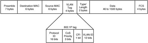 Table 3-1 defines the fields in the 802.1Q tag field.
Example 3-2 shows how a switch port is configured with an 802.1Q trunk on a Cisco Catalyst 3550 switch. Example 3-2. Configuring an ISL Trunk on a Port
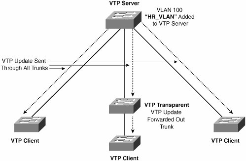
Exploring MAC Learning with Multiple VLANsFigure 3-3 illustrates how MAC learning is performed after segmenting the network from Figure 3-1 into two different VLANs. Figure 3-3. MAC Learning with Two VLANs and Inter-VLAN Routing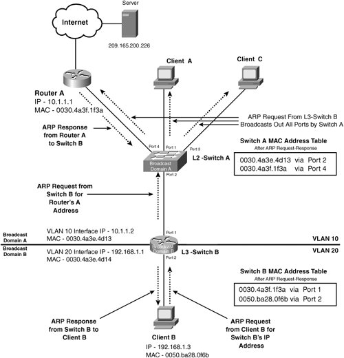 VLAN 10 is configured on all ports of Switch A and Port 1 of Switch B. VLAN 20 is configured on Port 2 Switch B. Switch B is configured with a VLAN interface for VLAN 10 and another for VLAN 20 in order to route between the two VLANs. Note For more information on IP routing, see the section "Understanding IP Routing" later in this Chapter. Because Switch B is a Layer 3 switch, it maintains its own ARP cache in addition to a Layer 2 MAC table and serves as the default gateway for Client B. For example, Client B sends an ARP request for Switch B's IP address, instead of Router A's IP address as shown previously in Figure 3-1. Therefore, Switch B originates an ARP request for the IP address of router A in order to determine where to route the client's upcoming application request to the Internet. Notice how the resulting MAC table for Switch A is slightly adjusted in Figure 3-3 from Figure 3-1. Switch A no longer has an entry for Client B but instead has the entry [0030.4a3e.4d13 via Port 2] for the VLAN 10 interface of Switch B. VLAN Trunking ProtocolVLAN trunking protocol (VTP) is used to manage the creation, removal, and availability of VLANs in a switched network. You can configure your switches with VTP by assigning them as servers, clients, or transparent. You can create, change, and delete VLAN information on a VTP server, including the VLAN number and name. The VLAN information is permanently stored in a VTP database within non-volatile RAM (NVRAM) of the VTP server. VLANs are not created on VTP clientsVTP servers advertise the VLAN information to the VTP clients over trunk links, in the form of VTP messages. The VTP clients store the information dynamically in RAM and in turn forward the VTP message out all VLAN trunks, except the trunk that the VTP message was received on. You must add VLANs to the VTP server before assigning the VLANs to ports on either VTP servers or clients. However, switches assigned as VTP transparent do not participate in VTP but will relay the VTP updates to other switches in the domain. You must create and remove VLANs locally on transparent switches. The VLANs are stored in NVRAM on the VTP transparent switch, but they are not advertised to the VTP domain. Figure 3-4 illustrates how VLAN information is advertised over VLAN trunks using VTP. Figure 3-4. A Simple VTP Domain with a VTP Server Sending Updates to VTP Clients In this example, a new VLAN is added to the VTP server for the human resources department. The update is sent out on all VLAN trunk ports, to all switches in the domain. The transparent switch simply forwards the update to its downstream neighbor. Important facts that you should know about VTP are
|
EAN: 2147483647
Pages: 178