Network Topology
|
| < Free Open Study > |
|
A network’s topology is the actual physical layout of the network. The topology of a network is based on factors such as the number of workstations and servers required, the communication methods that will be implemented, and the cables and specialized equipment that are available. As you will learn soon, network-related security issues also play a major role in the way networks are constructed physically.
The three standard network topologies are as follows:
-
Bus
-
Star
-
Ring
By the end of this chapter, you should be able to identify the three main typologies and the cable types associated with each.
The three topologies and their associated characteristics form the framework from which most networks are based. All three topologies are described in the following sections.
Bus
An Ethernet bus topology, otherwise known as a linear bus, is a topology designed for a limited number of computers that are typically attached to a single wire or trunk in a straight line. As you add more workstations to a bus topology, performance decreases. Figure 4.1 displays a typical bus topology.
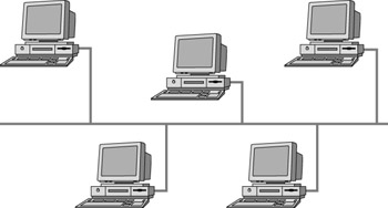
Figure 4.1: A linear bus topology network
The main type of cable implemented in a bus topology network is 10Base2. Devices called terminators must be placed on both ends of a bus network or wire to keep the data signal placed on the wire from bouncing back and forth. This phenomenon is referred to signal bounce. All computers on the bus listen for the data signals. If the signal is addressed to a particular workstation, the workstation accepts the signal. If the physical wire or connection that makes up the bus topology is damaged or breaks, the individual computers on the bus will still be able to operate independently but will not be able to accept data signals and communicate with other computers on the bus network.
Bus and star networks utilizes CSMA/CD media access control methods to place a signal on a wire. CSMA/CD is an Ethernet error detection method used to ensure proper data handling on a wire.
BNC and BNC barrel connectors are used to attach a bus cable to a device or connect one piece of the bus cable to another. A device called a repeater is used to boost or regenerate the signals placed on a 10base2 or bus network. Adding a repeater to your bus can extend the length of your entire bus network. For distances associated with a bus network, refer to the cabling section later in the chapter.
The following points are important to remember regarding a linear bus topology:
-
Use less total cable length than a star topology network.
-
Failure of one computer fails does not prevent the network from functioning. If there is a break or failure on the main bus cable, the entire network will fail.
-
Terminators are required at both ends of the bus backbone cable.
-
Problems are difficult to isolate on a bus network if the entire network fails.
Star
A star topology physically looks like a star. See Figure 4.2 for a simple star topology network. A star topology utilizes a central device, which can be a hub, a router, or a switch. These components will be discussed in detail later in the chapter. For now, we will refer to a simple hub for the central connection point in a star network.
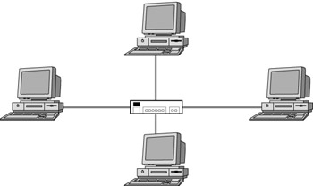
Figure 4.2: A star topology network
All devices in a star topology network are typically connected to a hub with twisted pair, otherwise known as 10BaseT cable. A star topology network is known to require large amounts of cable for larger networks. The hub provides a central location where the network can be managed and tested. If one computer fails on a star network, the other computers connected to the hub can still function and communicate with one another. However, if the hub fails, all communication between devices will cease.
The following points are important to remember for the exam regarding a star topology network:
-
Use a centralized hub, router, or switch to manage network traffic.
-
Failure of the central connection device causes the entire network to fail.
-
Failures are easier to troubleshoot. It is also easier to add and remove devices from the network through use of a central connection point.
-
Expense is greater than a linear bus network.
Ring
A ring topology network is best understood by picturing an actual circle of cable. Workstations and servers are all connected to the circle of cable. There is no end to the ring network that must be terminated. Each computer attached to the circle regenerates the data signal sent in the form of a token. The circling of the token to each of the servers and workstations on the ring is known as token passing. If the wire that makes up the ring is damaged, all network activity on the ring will cease. Keep in mind, IEEE 802.5 is a standard that applies to token passing technology. Figure 4.3 displays a simple token ring topology.
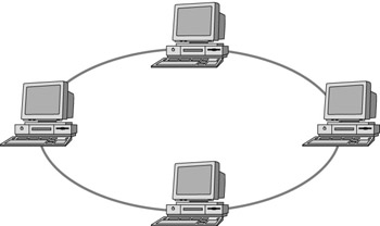
Figure 4.3: A ring topology network
The following points are important to remember regarding a ring topology network:
-
Nodes (systems) attached to the ring act as repeaters that boost the signal’s strength as it travels around the ring.
-
Breaks in the ring’s structure cause the entire network to fail. If a network interface card (NIC) connected to the ring goes into an error state or is set to the wrong ring speed, the entire ring might fail.
-
Ring technology is considered expensive.
FDDI (Fiber Distributed Data Interface) Ring
An FDDI (Fiber Distributed Data Interface) ring is based on a set of ANSI (American National Standards Institute) standards for data distribution over fiber optic cable in a network. An FDDI ring is typically composed of two fiber optic token rings. An outside ring is used for the primary transport of data and an inside ring acts as a backup if the primary ring fails. The following are important facts to remember regarding FDDI rings:
-
Serve often as network backbones for WANs.
-
Can support thousands of users.
-
Capable of up to 100Mbps data transmission speeds.
-
Travel of data in opposite directions in a dual FDDI ring topology—one ring clockwise, the other ring counterclockwise.
-
Use of token passing technology.
-
Has a distance capability of up to 200km (124 miles) in a LAN environment.
Mesh
In a mesh topology network, all nodes (systems) are connected to each and every other node on the network (Figure 4.4). If the connection from one node to another node fails, a different route can be taken to access other nodes on the mesh network. This redundancy makes a mesh network one of the most reliable topologies available. Mesh networks are classified into two types of topologies. The more expensive but more redundant full mesh topology and the less expensive not as redundant partial mesh topology. Typically, a partial mesh topology is used as a backbone to connect full mesh topology networks.
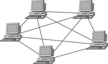
Figure 4.4: A mesh topology network
Intranet
An intranet is a network that is considered private and separate from the outside world. It exists to connect the workings of an internal network. Typically, separate internal networks or LANs are connected to a larger internal WAN through dedicated leased lines using connections such as T1 or DS3. Gateways and firewalls are usually implemented to allow users within an intranet to connect outside of the network.
Extranet
Allowing outside vendors, suppliers, and clients access to internal network resources and information has become necessary to and productive for the daily operations of most modern businesses. When part of an internal network or intranet has been made accessible to outside sources, that part of the internal network is referred to as an extranet. Access to the internal network typically requires use of public telecom technologies as well as a high level of security. This usually includes encryption and digital certificate technologies, as well as the use of firewalls.
VLAN (Virtual LAN)
A VLAN is a network of systems where any single system can reside on a separate network but be configured as though it were on the same network as other systems in the VLAN. In other words, systems in a VLAN appear and work as though they are all on the same subnetwork. In reality, they are located on separate or different subnetworks. A great advantage to using a VLAN is that systems can be moved within a VLAN without having to make hardware adjustments. Companies such as 3com and Cisco Systems offer VLAN software.
|
| < Free Open Study > |
|
EAN: 2147483647
Pages: 136