6.2 Domain Objects
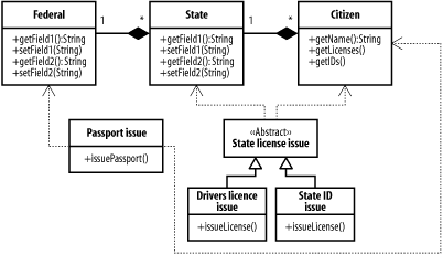
| The patterns in this chapter focus on important aspects of business tier development. We start with the Domain Object Model, which is at the heart of most large J2EE applications. The Domain Object Model defines an object-oriented representation of the underlying data of an application. The benefits of this approach should be familiar by now: the tiers integrating with the business tier become simpler and are decoupled from the implementation of the business tier, allowing changes to the resource layer level implementation without affecting the UI components. Business processes can be included in the domain object model via methods attached to the entity objects in the model or to specialized objects. We'll also look at the Composite Entity pattern, which provides a guideline for building domain objects in an efficient way. The goal is to balance flexibility and efficiency by creating object representations that can be used in the most efficient way. 6.2.1 Domain Object ModelThe domain model is the portion of the business tier that defines the actual data and processes managed and implemented by the system. The process for creating an effective domain model varies depending on the project, the information available, and the future requirements of the system. The Domain Object Model pattern is central to most J2EE applications. The pattern is fundamentally simple: create a Java object model that represents the concepts in the underlying domain. This may seem obvious, and you may even question whether it should be considered a pattern at all. It's certainly intrinsic to EJB. On the other hand, it's possible to build applications with J2EE technology that don't use a formalized domain model at all, and it's possible to build a domain object model without using EJB. Many web applications get along fine without a domain object model. They keep their domain model entirely in the database component, never building an object representation. In this case, the model is relational rather than object-oriented: two-dimensional tables full of data, linked to other tables via a set of shared keys. The application updates the model by executing SQL statements directly from servlets, and produces HTML pages the same way. In some cases, business process information is also held in the database, in the form of stored procedures, or it is embedded in the servlet tier. In contrast, a domain object model represents the application's entities (which would otherwise be found in database tables) and processes (which would otherwise be scattered throughout the application). The ultimate repository may still be a relational database, and the objects that make up the model are responsible for persisting themselves to the database in an appropriate way. The presentation tier can access the Java objects instead of manipulating the database directly. In building a domain object model, we translate the business model into object terms. Figure 6-2 shows a simple domain object model for a system that issues government IDs. We'll leave the potential civil liberties issues inherent in this system aside, and focus on the domain modeling issues instead. We have three classes, one for the federal government, one for the state governments, and one for citizens. The federal government can be associated with multiple state governments, which can have multiple citizens. We also have four classes that perform business activities. The Passport Issue class uses the federal government and the citizen classes to issue a passport. The State License Issue class is abstract, and is extended by two other classes that issue particular kinds of state ID cards. Figure 6-2. Domain Object Model for government IDs This is a simple example, but it's amazing how many development projects get going without nailing these relationships down as much as possible at the start. Next, we'll take a look at how we might get to this model.[2]
6.2.2 Building an Object ModelThe analysis process for building an object model depends on the project, resources available, and processes within a particular organization. We find the following general approach to be both prevalent and useful. Building an object model for the domain requires a solid understanding of the business foundations underlying the system. Often, developers aren't in a position to supply this information on their own, particularly when they're coming in as consultants or independent contractors. The information has to come from the business users. This process isn't always simple, since the users may be busy, unavailable, or in the case of a company developing a new product, nonexistent. Even when they can be tracked down, they don't always know what they want.[3]
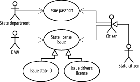
6.2.2.1 Define the visionThe place to start is the business requirements for the software. Whole books have been written on the subject of gathering requirements effectively and presenting them as usable specifications. See, for example, Software Requirements by Karl Wiegers (Microsoft Press) and Writing Effective Use Cases by Alistair Cockburn (Addison-Wesley). We find it helpful to start by creating a vision statement for the domain model. This statement, which can be exceedingly brief, should describe a high-level vision for the domain model, including its purpose and scope. An example might read: "An inventory, customer, and sales management system for use by all of the web-based applications and internal systems at XYZ Corporation." More than a paragraph is probably overkill. The vision statement should address current requirements and potential future needs, but it should take care not to overload the project with speculative features. Vision statements help to boost morale, too. Developers, like most corporate citizens, like to know that they're working on something that's been thought out in advance. A vision statement also helps keep change requests under control, since potential alterations can be evaluated in the context of the product vision. Let's build towards the domain object model introduced in Figure 6-2. We're going about it a bit backward, since we've already shown you the model, but stick with us here. In our case, the vision statement might be, "The system will manage and issue official forms of identification for every citizen in the United States. It will support the major forms of identification issued by the federal and state governments." 6.2.2.2 Gather the user casesThe next step is to identify the use cases for the application or applications that will follow the domain model. In some situations, these use cases will be in the style introduced in Chapter 2. In other cases, you may need to work backward from a requirements specification. Working from requirements specifications can often be harder than working from pure use cases: the author of the specification may have unknowingly made some design decisions as he spelled out exactly what the system should do. Watch out for these implicit assumptions. Our example National ID system might have several use cases, including "Issue Passport," "Verify Citizenship," and "Issue State License" (generalized from "Issue State ID" and "Issue Driver's License"). There are several actors involved, as well: the State Department, the local DMV, and citizens of the state and the country. The State Citizen actor generalizes to a Citizen, and the two use cases for issuing state IDs generalize to a parent use case for issuing state level licenses. Figure 6-3 shows a simple use case diagram for this application. Each use case, as we discussed in Chapter 2, needs to be specified with more than a name. For example, the Issue Passport use case might include the following steps:
The Driver's License use case is similar, but involves verification that the applicant has passed her driving test, has a clean driving record, and is a citizen of the state in which she is applying for a license. Figure 6-3. National ID system use cases 6.2.2.3 Find object candidatesThe next step is to identify object candidates for each use case. In our example, we need to identify citizens for each use case, and we need to store information about who has been issued a particular ID; a Citizen object is an obvious choice. The State Department and the DMV could have their own objects, but we don't need access to any other aspects of the State Department or the DMV. We do need to know which states citizens are citizens of, so we have a State class, and a Federal class to hold the states. Citizenship is constrained via a business rule within the domain model: a citizen is a citizen of any polity in whose object they are contained. So, all citizens are federal citizens, and each citizen is also a citizen of exactly one state. This is also an example of a domain boundary for the system: it only applies to the United States, or other countries that assign citizens to two hierarchical categories for purposes of licensing. Countries that devolve these responsibilities to, say, a city within a state would need to modify the model. We define these relationships in the class diagram by making the associations between Federal, State, and Citizenship objects composite associations, rather than simple associations. Using this approach builds the business rule directly into the domain model, and also means that we've made a trade-off: supporting multiple citizenship or state citizens who are not federal citizens would be difficult in the future.
We now have the three domain objects in the system: the federal government, the state governments, and the individual citizens. These are our "nouns." We also define four classes, one of which is abstract, to represent the use cases we're implementing. In this case, we've kept things relatively simple and built a class to handle each activity. The two state-level activities share a superclass that contains methods common to both: for instance, a method to verify state citizenship. We're now more or less done: the resulting class hierarchy is the one we introduced in Figure 6-2. In designing all of these classes, we've tried to keep one of the fundamental principles of object-oriented programming clearly in sight: the separation of responsibilities. Each class should be responsible for as little as possible, and should only be responsible for activities that bear on it directly. For example, the Citizen class in the example above includes methods to retrieve the licenses and IDs created by the other classes, but doesn't include mechanisms for issuing passports and drivers' licenses. While these activities affect individual citizens, carrying them out is not the citizen's responsibility. However, the Citizen class might include a method, such as verifyResidence( ), which could be used in the license issue process.
6.2.2.4 Implementing a domain object model in J2EETraditionally, domain object models in J2EE are based on EJBs. However, just because EJBs exist doesn't mean that you need to use them. EJBs have two major advantages over Plain Old Java Objects (POJOs). First, they can be accessed remotely: the EJB server can be located on one system while the client is located on another. In design parlance, this means they are remoteable. Second, EJBs are transactional: a set of operations performed on one or more EJBs can be made contingent on the success of all the operations. We'll discuss transactions in much more depth in Chapter 10. For enterprise applications with a Swing GUI interface, the ability to access objects hosted remotely is often vital: without this ability, the client will have to maintain its own connection with the resource tier, and changes to the business tier implementation will involve updating every single deployed client, creating an access control and scalability nightmare. EJBs often make sense when you need a coarse-grained entity model, remote access, and integral transaction support. Typical situations in which EJBs are appropriate include applications that are geared toward frequent and complex transactions, applications in which the domain model will be accessed by a number of systems at once, either via clustered web servers or a large number of Swing GUI clients, and applications that spread transactions across multiple services (databases, messaging servers, etc.). For more on when to use and not use EJBs, see the "Everything Is an EJB" antipattern in Chapter 12. Plain Old Java Objects can be a little more work to code, but they are easier to deploy, since they don't require an EJB container. Because they don't provide a remote interface, they can be more efficient than EJBs when distributed capabilities aren't required. For the same reason, regular objects lend themselves to a more finely grained object model than EJBs do, since each regular object maps to a single object instance (EJBs require four or more). In many web applications, the same server can run the POJO model and the servlet container, keeping everything in the same JVM. The tradeoff is that you need to support transactions on your own, rather than delegating to the EJB container (we'll look at strategies for dealing with this in Chapter 10). POJO models can also be difficult to cluster effectively, although the greater efficiency of this approach for many applications can reduce the need for clusters in the first place, at least for scalability purposes. Most modern databases, running on appropriate hardware, easily keep up with the load imposed by a high volume site, assuming the data model was designed properly. Since a POJO object model lives in the same JVM as the web tier, it's easy to cluster several web servers and point them to the same database, provided you have the right concurrency design. The other nice thing about a POJO object model is that you're not stuck with it. If it turns out that you need an EJB interface after all, it's relatively easy to wrap BMP Entity and Session Beans around your existing objects and move them into an EJB server. Some applications don't need to expose the entire data model (as found in the database) as Java objects. We'll look at strategies for interacting directly with relational databases in the next chapter. 6.2.3 Composite Entity/Entity Façade PatternOne common mistake is mapping each table in the underlying database to a class, and each row in that table to an object instance. It's easy to fall into this trap when developing Enterprise JavaBeans using Container Managed Persistence, but it can happen just as readily with non-EJB technologies like Java Data Objects, O/R mapping tools, or coding from scratch. A good data model can actually make this temptation worse. In the EJB world, a profusion of entity beans has severe performance consequences. Each bean requires not one but several objects to support it, and the server must do more to maintain the integrity of each bean and manage resources effectively. Since clients need to access a large number of distinct entity beans in order to accomplish any given task, communication overhead causes performance degradation proportional to the number of objects involved (see the Round-Tripping anti-pattern in Chapter 12). These issues can be ameliorated using the Composite Entity pattern, which is also known as the Entity Façade pattern.[4] We'll see a few more façade patterns over the next couple of chapters, all based on the GoF Façade pattern. The Façade pattern provides a simple interface to a complex system: one object fronting for several objects or several database tables.
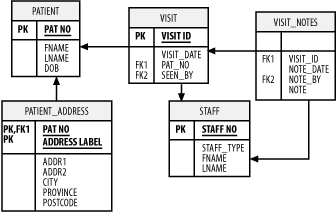
Composite entities are simply coarse-grained domain objects. When implementing a system using EJB, rather than mapping one bean class to each table and one bean instance to each row, a Composite Entity will collect information from multiple tables and multiple rows into a single entity bean. The entire domain model may still be represented, but not as a direct mapping to the underlying persistence structure. Composite entities aren't the exclusive province of Enterprise JavaBeans. Any object representation of a domain model entity can use this approach to make itself more efficient and easier to use. Clients accessing composite entity objects have an easier time manipulating the domain model, since they have to manage fewer EJB instances at once. This is particularly the case when the database design has already been defined and can't be changed, either due to legacy system considerations or conflicting requirements. On the implementation side, using a composite entity allows you to improve performance in at least two ways. First, the smaller number of entity beans reduces the amount of network activity required between the client and the server, as well as between the various beans within the server. With fewer objects in memory, a given quantity of computing resources can handle that many more connections. Second, mapping multiple tables to a single bean allows you to take advantage of the capabilities of the underlying database to merge information at the SQL level rather than the object level. 6.2.3.1 A composite entity schemaLet's look at a simple composite entity schema, which we'll use in the next few chapters. The example is the core of a data structure for managing patient visits at a small hospital. We will track patients, patient addresses, patient visits, notes recorded at each visit, staff members involved in a visit, and notes on the procedures that were performed. There's no central table in this example. Instead, the tables queried depend on the needs of the application. The database structure is normalized: any time an entity within the database, such as a patient, visit, address, or staff member is referenced in more than one place, it is pulled out into a new table with a separate primary key (we'll talk more about primary keys in Chapter 8). Similarly, data with uncertain cardinality[5] is also pulled into separate tables, with a reference back to the primary key of its logical parent. For example, a patient may have multiple addresses: Home, Office, Billing, Insurance, and so forth. Rather than add fields to the Patient table for each of these, we create a new table, PATIENT_ADDRESS, linked to the Patient table via a primary key. This allows us to add all the addresses we want. We do the same thing with visit notes, which are stored in the VISIT_NOTES table and linked to the VISIT table and the STAFF table (since there can be multiple visit notes per visit, and each visit note could be created by a different staff member, such as a radiologist or nurse). Figure 6-4 shows an illustration.
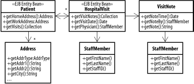
Figure 6-4. Patient and visit database schema The simplest way of mapping this schema to an EJB object structure is to create a new EJB entity bean type for each table. This process allows us to easily use Container Managed Persistence, and allows simple remote updates to each type of data. On the other hand, it results in a profusion of entity beans. A healthy patient probably averages one or two visits a year, and sick patients will generally visit much more often. So the average number of yearly visits may be closer to four or five. Each visit might have 10 or more visit notes associated with it, depending on what procedures were performed. That means each patient could produce 40 or 50 new entities a year. These add up fast, since a single hospital might serve 10,000 or more patients (most of them just pop in for 20 minutes a year). Of course, a well designed EJB container will manage to avoid keeping most of this material in memory at all times, but it's still an awful lot of objects. That's the problem at the macro scale. The An-Entity-Bean-for-Everything approach also causes problems at the micro scale. Remember that each time you access a remote EJB, you incur a network performance penalty that can be measured in milliseconds. A web page that requires accessing 40 different EJBs will take much longer to generate than one that requires 4, with a corresponding impact on your budget for application servers. Figure 6-5 shows the hospital visit object model using a set of composite entities. There are still two classes of entity bean: the Patient bean and the HospitalVisit bean. The HospitalVisit bean contains objects representing the visit date, the attending physician, and all of the procedures performed during the visit. The Patient entity bean contains an Address object, and has a one-to-many relationship with a set of HospitalVisit entity beans. Figure 6-5. Object model with composite entities When the EJB container instantiates the HospitalVisit bean, the bean loads all of the associated visit notes, as well as the staff information for both the attending physician and for each visit note. This process may take two or three queries, but it can be optimized for performance. For example, the visit note information and visit note staff information can be retrieved with one SQL statement. Here's a simple approach to building out the objects (we'll see much more of this in Chapter 8). // Assume visit_id variable containing the visit primary key Connection con = getConnection( ); Statement stmt = con.createStatement( ); ResultSet rs = stmt.executeQuery("select VISIT_DATE, FNAME, LNAME from " + "VISIT, STAFF WHERE VISIT.VISIT_ID = "+visit_id+" AND STAFF_NO = SEEN_BY"); if(rs.next( )) { // ... Read visit information } rs.close( ); rs = stmt.executeQuery("select NOTE_DATE, NOTE, FNAME, LNAME from " + "VISIT_NOTES, STAFF where VISIT_ID = " +visit_id+" AND STAFF_NO = NOTE_BY"); while(rs.next( )) { // load visit notes } // etc. We leave the Patient and HospitalVisit objects as entity beans because they might need to be associated with a variety of other objects (such as bills or HMOs). We also need something that external components can access. The individual procedures and addresses, on the other hand, are not necessary outside the context of the entity beans that control them. The StaffMember class is shown twice on the diagram to indicate that a particular instance of the object isn't shared between visits and notes. Like the VisitNote and Address objects, a StaffMember object is created at need by the parent object. In EJB applications, composite entities are more difficult to implement using Container Managed Persistence, although it's certainly possible. For easier portability, it often makes more sense to use Bean Managed Persistence. In the next chapter, we'll look at some database-related patterns that make it easier to build both BMP and POJO entity objects, and in Chapter 9 we'll see some patterns designed to further reduce network traffic and to improve the separation of the entity model and the business logic. |
EAN: 2147483647
Pages: 113
