Defining Relationships
| Relationships allow for a logical link between one entity and another. A relationship in an ER model connects the data elements of two entities containing information about the same real-world element. The primary entity in a relationship provides for some of the data, and other entities supply further related data. A relationship definition states how two entities are connected. When the physical structure is developed, the entity connection becomes foreign key connections to primary keys. In the modeling process, we attempt to discover which things are related to one another and how they are related within the business problem we are modeling. Relationships are usually defined as links connecting entities, based on the number of data elements in one entity that are related to one or more elements in the other entity. The number of related elements is known as the cardinality of a relationship. Relationships can be one of three types: one-to-one, one-to-many, and many-to-many. Each relates to a different configuration linking two entities. One-to-One RelationshipA one-to-one relationship occurs when one row or data element of an entity is associated with only one row or element in the second entity. This type of relationship is used most often when an entity has an extraordinarily large number of attributes, so the entity is split in two to make it easier to manage. Also, we might want an extra entity when developing the data's physical storage locations. Separating seldom used data from more frequently used information can result in faster data retrieval and updates. One-to-Many RelationshipOne-to-many relationships exist when a single instance of an entity (the parent entity) relates to many instances of another entity (the child entity). One-to-many relationships are a natural occurrence in the real world; for example, a customer has many orders, and a manufactured product has many components. An HMO has many patients and, therefore, represents this kind of relationship.
Many-to-Many RelationshipA many-to-many relationship occurs when many rows or data elements in an entity are associated with many rows or data elements in another entity. This type of relationship is not uncommon in the real world, but most database servers do not directly implement many-to-many relationships. A many-to-many relationship is implemented using three entities. The two main entities are connected by using a third entity. The third entity contains keys connected to the other two entities. For example, a Doctor has many Patients, and Patients could have many Doctors; likewise, a Patient could take many Drugs, and each Drug could be taken by many Patients. Figure 8.3 illustrates this relationship and other many-to-many relationships in the case study. Figure 8.3. Billington's many-to-many relationships.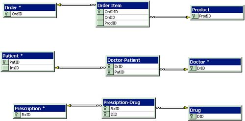 Identifying RelationshipsRelationships are implemented as parent and child entities. In all cases in the ER model, a key attribute from a child entity is attached to a related key value in a parent. All relationship cardinality is implemented in this way. This means that whether you have a one-to-one, one-to-many, or many-to-many relationship, you always have the key attribute of the child related to a parent. As noted previously in this chapter, many-to-many relationships exist when many instances of one entity are related to many instances of another entity. The reason many-to-many relationships are implemented a bit differently is that the ER model does not support many-to-many relations. Nonetheless, we can do so by creating two one-to-many relations and connecting them to a new entity. This new entity is known as an associate entity or a join entity. Resolving many-to-many relationships involves creating two one-to-many relationships from each original entity onto the associative entity. Take the many-to-many relationship between Doctors and Patients, for example. A Patient can have many Doctors, and a Doctor has many Patients. This many-to-many relationship needs to be resolved by creating an associative entity, DoctorPatient (Dr-Pat in Figure 8.4), and then linking a one-to-many relationship from the Doctor and Patient entities to DoctorPatient. Figure 8.4. The finalized draft of Billington's ER model. Setting up the relationships finalizes a draft of the ER model (see Figure 8.4). This draft will undergo modifications as the database approaches a physical design. At this stage of design, all the basic elements of the data model have been completed by using the ER approach, so you now have a working model that enables you to proceed with development. A general listing of attributes for each entity and the relationships between these entities is an important springboard for progressing through the database design to the eventual completed system. Figure 8.5 represents an example of a completed database design for Billington. Figure 8.5. Billington's proposed database design. |
EAN: 2147483647
Pages: 175