PA-RISC I/O Architecture The PA-RISC I/O architecture has specific requirements for all PA-RISC systems. These are designed to provide a standard set of rules for how the I/O hardware works and communicates with other components. Every PA-RISC system must have at a minimum at central bus to which must be attached at least one processor module and at least one memory module. If the system has more than one processor or more than one memory module, they all reside on the central bus. There are also a number of possible native busses. A native bus is one that adheres to the PA-RISC I/O architecture. As hardware has evolved since the introduction of PA-RISC, a number of new native busses have been introduced. One of the earliest of these was the HP Precision Bus (HP-PB), also called the native I/O (NIO) bus. Some others include the high-speed connect (HSC) bus, Gecko System Connect (GSC) bus, summit bus, and runway bus. Each provides different capacities and performance points, but all are native busses. In addition to the native busses, PA-RISC systems must be able to connect to a variety of busses that were not designed with PA-RISC in mind. These are known as foreign busses. Some examples are Extended Industry Standard Architecture (EISA), Peripheral Component Interconnect (PCI), and Versa Module Eurocard (VME). These busses are designed by a variety of non-HP organizations and are used on many types of systems beyond PA-RISC. Because they don't conform to the PA-RISC architecture, we have to have some hardware that adapts their interface to that of the PA-RISC system. These adapters, which connect native busses to foreign busses, are called bus adapters. It may also be desirable to connect between two different native busses, perhaps to expand capacity, for example. The PA-RISC I/O architecture specifies that a native bus can have no more than 64 modules on it. To get beyond this limitation, we can attach one native bus to another, much the way some people chain extension cords and power strips together to get more electrical outlets. The hardware that connects one native bus to another is a bus converter. Figure 10-1 shows a block diagram of a typical PA-RISC system. In this example, we have two processors and two memory modules connected to the central bus. There is also an I/O module connected directly to the central bus, along with a bus converter that connects to a native bus and a bus adapter that connects to a foreign bus. Figure 10-1. PA-RISC I/O Block Diagram 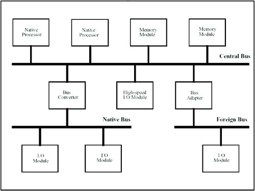
All of these components must be able to communicate with each other. This is part of what makes the I/O subsystem such a large and complex part of the kernel. IODC and PDC All native I/O modules provide an area of memory on the card known as I/O-dependent code (IODC). IODC normally resides in ROM on the interface card, but is frequently copied into main memory and accessed there. There are two components to IODC. The first is an area that contains information about the I/O module. By examining this information, the system can uniquely identify a particular type of module and determine how to interact with it. The second is a set of standard entry points that can be used to interact with the module. Not all modules provide all of these entry points. Some examples of these are ENTRY_INIT, which is used by the system at boot time to tell the card to initialize itself, and ENTRY_IO, which can be used at boot time to read or write through the module. This last is particularly important because this is how the kernel gets loaded into memory at boot time. In order for a device to be bootable, the I/O card it is connected to must have IODC that supports ENTRY_IO. Processor-Dependent Code (PDC) Similar in concept to IODC, each native processor also has an area of processor-dependent code (PDC). It contains a set of standard entry points to control and query the processor. Among these are entry points for resetting the processor (PDC_RESET), handling hardware errors or machine checks (PDC_CHECK), and handling transfer of control requests (PDC_TOC). PDC also provides entries for retrieving model information, controlling the system's chassis display, and managing the real-time clock. I/O Address Space PA-RISC uses memory-mapped I/O space. This means that there are no specific instructions for performing I/O in the system. Instead, all I/O modules take up a portion of the memory space, and the system uses LOAD and STORE operations to interact with the memory modules. The 32-bit and 64-bit address layouts are slightly different, but the concepts are the same. Figure 10-2 shows the 32-bit layout, and Figure 10-3 shows the 64-bit layout. Figure 10-2. 32-Bit I/O Address Space 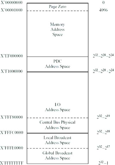
Figure 10-3. 64-Bit I/O Address Space 
Both address-space models reserve a portion of memory for PDC address space. In the 32-bit model this is from 0xEF000000 to 0xF0FFFFFF. In the 64-bit model, it is in the range 0xFFFFFFF0 00000000 to 0xFFFFFFF0 FFFFFFFF. This area of address space is reserved for use by PDC. Memory in this range can be used both for PDC code itself and for data storage. Both models also reserve a range of addresses for interfacing with I/O modules. In the 32-bit model this range is from 0xF1000000 to 0xFFFFFFFF. The 64-bit model has a range of addresses that correspond with the 32-bit ranges but with the upper bytes "F extended." This gives a range from 0xFFFFFFFF F1000000 to 0xFFFFFFFF FFFFFFFF. This range of 64-bit addresses is called the local I/O address space. In addition, the 64-bit model has a pair of ranges the make up the global I/O address space, which is accessible only by 64-bit processes. These ranges are from 0xF0000000 00000000 to 0xFFFFFFEF FFFFFFFF and from 0xFFFFFFF1 FFFFFFFF to 0xFFFFFFFF EFFFFFFF. As you can see from the figures, the 32-bit I/O addresses and the corresponding local I/O addresses in the 64-bit model are further divided into four regions: A general I/O space for addressing modules on the bus An area reserved for the system's central bus A local broadcast area for communicating with all modules on the bus A global broadcast area for communicating with all modules in the system.
The general I/O space is further divided according to the topology of the system. Each bus in the system is given a 256-KB chunk of the address space. This 256-KB chunk is then divided into 64 chunks of 4 KB each, one for each possible module on the bus. The module's space is divided into 64 register sets, each with 16 registers. Of course, not every module will use all 1,024 registers, but that is the space that is available to the module. These addresses associated with a module are known as the module's hard physical address. Now that we have all these addresses partitioned into busses and modules and register sets and registers, how do we know what to do to talk to an I/O module? That's the part that is unique to every type of module, and that's why every module type has to have its own driver. The system can query the IODC in the module, find out what kind of module it is, and assign it to a driver, and the driver then knows what registers are available and how to use them to communicate with the card. Modes of Operation There are two general modes of operation that can be used in communicating with an I/O module. The first is direct I/O. A direct I/O module cannot initiate a transfer of data on its own. In order for data to be transferred, the processor (or some other bus module) must explicitly do a LOAD or STORE operation. The only way a direct I/O module can initiate communication is by sending an interrupt to a processor. This puts some severe limitations on what can be done with a direct I/O card. The throughput on this type of card is low, and the demands on the processor are high because it has to be involved in every data transfer. However, there are some advantages too. Direct I/O is much easier to implement in hardware, particularly when interfacing to existing devices that are not designed with the PA-RISC architecture in mind. For this reason, they're also less expensive. For a low-speed operation to industry-standard devices, such as parallel and serial ports, direct I/O can be a good solution. When the need for performance is higher, then we turn to the other type of I/O card: direct memory access (DMA). A DMA I/O card can initiate its own data transfers across the bus, normally to and from a memory module. The processor can give a DMA I/O card a command such as "read" or "write" and a range of memory, and the card will transfer all the data in the range. When the operation is complete, it signals the processor with an interrupt. During the time the I/O is taking place, the processor is freed to do other work it doesn't need to get involved in the transfer until it is signaled that the transfer has completed. While this adds some complexity to the hardware on the module, it is an absolute necessity if we're to keep up with devices such as disks and tapes. PA-RISC further defines two different types of DMA modules. Type A DMA modules support data chaining. This allows the system to supply a list of data ranges rather than a single range. When the module finishes transferring to one range, it begins transferring to the next. The system is signaled when the entire DMA chain is complete. Type B DMA modules take this one step further. They allow chaining of the commands as well as the data lists. Thus, the processor can pass the module a list of commands to be executed, a list of the memory ranges with which to transfer the data, and let the module do all the work. The module then returns a completion list to the system indicating the status of the various commands. External I/O Interrupts Now we have I/O modules connected to system busses. Each module has a range of addresses through which the system can communicate with the module. How does the module go about getting the attention of the processor when it needs to? This is done through the External Interrupt process. Each processor has one control register called the external interrupt request register (EIRR) and another called the external interrupt enable mask (EIEM). These are 32-bit registers on a 32-bit machine and 64-bit registers on a 64-bit machine. Each bit in these registers corresponds to an external interrupt number. At boot time when the system is initializing the I/O modules, each module is instructed which interrupt number to use. All direct I/O cards use the same interrupt number: interrupt 3. They also send broadcast interrupts, meaning that when a direct I/O module sends an interrupt, all the processors get it. DMA cards, on the other hand, can each be given their own interrupt bit, and each can be assigned to a processor. When these cards send an interrupt, it's to a specific processor and to a specific bit on that processor. The programming of the modules and the interrupts themselves both take place in the same way: by writing to registers in the I/O space. Each module has a register called the IO_EIM register, which tells it where to send its interrupts. The processor writes a value to the IO_EIM register for each module as part of the initialization process. To generate an interrupt, the card writes to the IO_EIR register of the processor. Remember that a processor is just another module with an address on the bus just like any other. An I/O module writes to the processor's IO_EIR register to raise an interrupt. After each instruction, the processor performs a logical AND between its EIEM and its EIRR registers. If a bit is turned on in the EIRR and that interrupt is enabled by the corresponding bit being on in the EIEM, then an interrupt is generated. (The I bit in the Processor Status Word, or PSW, must be on too, enabling the overall interrupt system.) When the processor is interrupted, the first thing it does is turn off the I bit in the PSW, preventing any further interrupts until it is ready for them. It then branches to the first-level interrupt handler (FLIH) for the interrupt it has received. The address of this handler is found in an interrupt vector table (IVT), which is pointed to by the interrupt vector address (IVA) register (control register 14). Recall from Chapter 1, "PA-RISC 2.0 Architecture," that there are many types of traps and interruptions that the processor has to deal with. Each type is assigned a number; an external interrupt is a Trap Type 4. The address of the FLIH is computed as IVA + (32 * trap type). So for an external interrupt, the FLIH is found as the fourth entry in the table pointed to by the IVA. In HP-UX this is the routine ihandler(). Each processor in the system has its own interrupt control stack (ICS). When an interrupt occurs, the system switches to using the ICS rather than the user process's stack or the kernel's stack. It then saves the current system state onto that stack. Next, it calls one of three interrupt handlers: mp_ext_interrupt(), up_ext_interrupt(), or external_interrupt(). Which it calls depends on whether the system is multiprocessor or uniprocessor and whether or not the kernel debugger is running. We perform this little bit of magic by actually patching the code at boot time. That is, part of the boot-up process is to determine if we're a uniprocessor or multiprocessor system and go poke the right branch address into ihandler(). Regardless of which of the three error handlers is used, a certain set of steps is performed. The first is that we determine which external interrupt bit we're dealing with. The interrupt handler locates the highest priority unmasked interrupt to determine which to handle. It then sets that bit in the EIRR to off, indicating the interrupt has been received. Next, we mask off lower priority interrupts by modifying the EIEM. This holds off any lower priority interrupts until we're done with the current one. Now we can turn the I bit back on in the PSW, enabling interrupts overall. Finally, we're ready to call the correct interrupt handler for the external interrupt we received. The information on what to mask and where to find the specific handler is kept in a table called the eirr_switch. It is an array of struct eirrswitch: struct eirrswitch { void (*int_action)(); unsigned long eiem; void *int_arg; unsigned long io_int; };
Each entry in this array contains the pointer to the interrupt handler, the value that should be put into the EIEM, the argument to be passed to the handler, and a flag indicating whether or not the interrupt is an I/O interrupt. The flag is required because for an I/O interrupt, only the argument from int_arg is passed. For other interrupts, we also pass the bit number and a pointer to the save state. The values that get loaded into the EIEM are sometimes called the system priority level (SPL). The values for SPL are defined in the file /usr/include/machine/spl.h and are summarized in Table 10-1. Higher SPL levels are more restrictive. That is, they have fewer possible interrupts enabled. Table 10-1. SPL LevelsSPL Level | Alternate Name | Value |
|---|
none | SPLPREEMPTOK | 0xffffffff | SPL0 | SPLNOPREEMPT | 0xfffffff0 | SPL1 | | 0xffffffc0 | SPL2 | SPLSOFT | 0xffffff00 | SPL3 | | 0xfffffe00 | SPL4 | | 0xfffffc00 | SPL5 | SPLIO | 0xe1000800 | SPL6 | SPLSYS | 0x40000000 | SPL7 | SPLLWI | 0x00000007 |
We saw how hardware modules in the system communicate with each other. We looked at the address space of I/O modules, communication between modules using that address space, and the mechanics of how interrupts are generated and handled. In the next section, we take another step back and look at the framework that exists within the kernel for managing the various drivers. |