9.1 Agreeing on the Destination (Requirements)
First, get down to basics by listening to what your customer wants and then telling the customer what to expect. Each party understands exactly what the other party is talking about.
To get the ball rolling then, listen to what your customer wants. Right from the start the project can take a wrong turn , your customer could call you and you could do everything over the phone. Following is a list of ways you could undermine your project's chances of success at an early stage:
| |
|
The customer should have an idea about the destination, and before setting out you should be able to confirm with the customer at least the general direction. So, if you're lucky there will be a requirements specification. Here's an example.
ACME Widget Co.
1.0 I NTRODUCTION The ACME Widget Company produces world-class Widgets and is a market leader in all types of Widgety devices. The Widgetometer is a device for measuring the Widgetiness of the Widgets. The requirement is to produce a test system for automatically testing Widgetometers to the customer's test specification. 2.0 R ELATED D OCUMENTS Example of Widgetometer test specifications. 3.0 T HE W IDGETOMETER The Widgetometer is the new way of measuring Widgets in the field; each Widgetometer can measure two Widgets for their Widgetiness. The Widgetometer communicates by its displays, two 0 “10 V output ports, and RS232 communications. See the following schematic: 4.0 T HE T EST S YSTEM The system will test up to five Widgetometers against two gold-standard Widgets. The standard Widgets will need to be connected to both of the Widgetometer Under Tests ports. The requirement will be to take a reading from the Widgetometer's communication port and both of the Analog output ports. There is also a requirement to conduct a visual inspection of the display to confirm that the readings all agree. The standard Widgets will be calibrated, and the readings should agree with this calibration. The results will be recorded and stored in a retrievable format, and a printout of the test will be provided. 5.0 U SER I NPUT The user will plug the units into their test position and press a button to start the test. The units under test will identify themselves via the communications port. All the active test positions will then be tested to the customer's test specification for the part number. 6.0 S YSTEM O UTPUT On completion of a test, the UUT (unit under test) data will be archived. On completion of all the tests a printout will be produced. |
This document is usually accompanied by an initial requirements meeting. If no requirements document is made available prior to this, one should be discussed and produced from this meeting.
An Example Requirements MeetingThe meeting was held at the customer's premises and the following people were present:
Brief introductions are made and now we'll go straight to the nitty-gritty:
|
Now Derek has got to awake from his slumber and respond to the question from Millicent. He has various options; here are a few:
-
 Bluff.
 Yeah, LabVIEW can cope with anything you throw at it.
The problem here is that a bluff nearly always gets overtaken by reality. The other problem is that you are giving the customer the go-ahead to make changes without any consideration. Go this way, and you'll end up having end of project blues.
- Be strict.
We will need a complete specification before we can begin. Changes later on are far too expensive to rectify and will weaken the design of the software.
For languages like C or Pascal this is a reasonably valid path to follow, because if using these languages, the developer will disappear for three months and reappear with a finished product. This can be a recipe for customer disappointment if the requirements are not concisely and accurately defined and understood by all concerned parties. LabVIEW gives the advantage of Rapid Prototyping, use it!
You also have to consider that the only constant in software projects is change. As your customers learn more about the system they will have more suggestions and comments. It's a fact of life and we all have to cope with it. A large amount of work will pass you by with this attitude because in business customers don't want to wait.
Finally, a decent language combined with a robust design strategy will allow flexibility at a reasonable cost.
-
 Tell it like it is.
 LabVIEW is the language for writing the application, and the design of the application can be flexible or not. This depends on the effort put into the design and the inherent complexity of the system. We should design the system with flexibility in mind, but obviously there will be a cost consideration for large system changes. As long as the basic requirements stay the same we can reevaluate the process at each milestone.
We will also need to ensure that changes in requirements are communicated in an efficient manner and that only one person in your organization communicates them to us.
Go for it Developer man!
Anyway, we've chosen option 3 and the meeting continues.
|
The next step after the requirements have been communicated, is for you to tell what the customer is going to receive. This could be in the quote, contract, or as we like to call it, the target specification, and it should be regarded as your promise to the customer.
This is a communication- intensive process, so be prepared to talk to your customer. For example, it's a rare event when you get a requirement specification with no gaps in it. In this case there is little mention of the data to be collected by the system. Call them and clarify before you quote!
Derek's Software Co.
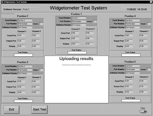
1.0 I NTRODUCTION This is a response from Derek's Software Co. to ACME Widget Company document number RS_WATE10001 Issue 1.00. That document expressed the need for a system to automatically test Widgetometers to a customer's test specification. 2.0 R ELATED D OCUMENTS Requirements Specification RS_WATE10001 Issue 1:00 Schematic of Widgetometer Test System DRG_WATE10001001 Issue 1:00 3.0 S OFTWARE, O PERATING S YSTEM, AND H ARDWARE The system will be written in LabVIEW version x.y and will work on Windows 2XXX operating systems. All source code will be provided as part of the contract. The software will need a minimum of the following to run satisfactorily: C OMPUTER
Associated plugs, cables, and wiring do not fall into the scope for this target specification. M EASURING S YSTEM DC Voltage Accuracy of better than ± 0.5% and a resolution better than 1 m V. C OMMUNICATIONS Communication will be RS232, 7 or 8 data bits, 0 or 1 start and stop bits, odd, even, or no parity. Data transfer rate will be between 2,400 and 19,200 baud inclusive. Protocol to be established. 4.0 U SER I NTERFACES The main display will contain all of the information from the system. Control buttons will be along the bottom of the screen. [Exit] stops and unloads the program. [Start Test] will commence testing. A dialog will be displayed to allow the user to enter any data that cannot be taken automatically from the units under test. The test sequence will be quick enough to remove the necessity of an abort test function. Test stage details will be displayed in the central display area. 5.0 T EST S CENARIO There will be a button that will allow the user to log in and out of the system. [Exit] and [Start Test] will be disabled when no one is logged in. When testing, the [Login] button will be disabled. The units will be loaded into the test system and [Start] pressed on the main screen. The test type dialog will be displayed and a test type selected or new test type entered. The test type will define the limits applied to each test. The unit details will be taken from the serial ports of all the units available, and any test positions that do not respond will be ignored. The units will then be connected in order to the two standard Widgets and their readings taken from the serial ports as well as the analog ports. A dialog will also be displayed that will request the readings from the Widgetometer displays. The data for each test will be stored on the completion of that unit's test. When all the tests are complete a test report will be printed. 6.0 T EST R EPORT F ORMAT
7.0 S TORED D ATA F ORMAT Data Stored . . . The file will be Comma Separated Text File, and the directory structure and name will correspond to unit serial number and date.
8.0 P ROJECT M ILESTONES AND R ESULTS
| ||||||||||||||||||||||||||||||||||||||||||||||||||||||||||||||||||||||||||||||||||||||||||||||||||||||||||||||||||||||||||||||||||||||||||||||||||||||||||||||||||||||||||||||||||||||||||||||||||||||||||||||||||||||||||||||||||||||||||||||||||||||||||||||||
Accompanying the target specification should be the test plan. This will be the instrument for confirming that the destination has been reached.
Derek's Software Co.
1.0 R ELATED D OCUMENTS
2.0 A CCEPTANCE T ESTING These tests are to confirm the system is satisfactory to the customer's requirements document (RS_WATE10001 Issue 1:00). 2.1 T EST E ACH P OSITION FOR A U NIT L OADED AND A U NIT N OT L OADED Take a unit with known attributes and load into position 1 and run the test. Move to position 2 and repeat, move to position 3 and repeat, move to position 4 and repeat, and move to position 5 and repeat. Confirm that the loaded tests agree with known values and the unloaded tests report an error.
2.2 T EST M EASUREMENT Q UALITY AND R EPEATABILITY Take five units with known attributes and fully load the test system and run a test. Confirm that the tests agreed with known values. Repeat the tests five times and confirm that readings do not drift beyond acceptable limits.
2.3 T EST EACH CRITERIA FOR A PASS AND FAILURE CONDITION For positions 1 and 5 set the limits to fail on all the parameters and then all the parameters individually.
2.4 C ONFIRM F ILE F ORMAT O KAY
2.5 C ONFIRM F ILE D IRECTORY S TRUCTURE O KAY, E SPECIALLY AT THE B OUNDS OF M IDNIGHT, M ONTH, AND Y EAR C HANGEOVERS. Confirm that the file directory structure agrees with the system time and date. By adjusting the system date and time confirm that new directories are generated correctly for the midnight changeover, month changeover, and year changeover.
2.6 C ONFIRM P RINTOUTS O KAY Check that the details on the printout agree with the data taken and that the format corresponds with the format described in the target specification.
|

Finally, we suggest the use of a prototype to better elicit requirements. However, this is usually only realistic at the requirements stage if the project has a separate cost feasibility stage. Alternatively, this can also be done as part of the design process to fine-tune the requirements. For your own sanity be prepared. Even if your software eradicates poverty from the world there will be someone who complains about the font!
Without a target specification your customer will not have confidence in what he or she is getting, and without a test plan the project will have no closure. You know what you are producing and your customer knows what he or she wants. A project will only be successful if everyone agrees.
So to summarize, the target specification should describe the key functionality of the system, and the test plan should list the tests that will establish that this functionality has been met.
In our journey these documents are the backpack , walking boots, food, compass, and map.
| |
| Top |
EAN: 2147483647
Pages: 66