OnNow Initiative
In an attempt to standardize (read: abstract) the various approaches to power management, Microsoft developed the OnNow Initiative. This specification builds on the capabilities of the hardware, providing a common platform for the various Microsoft operating systems to exploit. The OnNow initiative abstracts the power management capabilities of the system (mainboard) and devices. While individual devices may incorporate many clever powering schemes, the OnNow model describes distinct power states that a device or system can occupy at any given time. Power StatesA system exists in one of six power states, designated S0 through S5. The meanings are described in Table 10.1. The overall state of the system largely restricts the maximum power state of individual devices. Devices, meanwhile, occupy one of four power states, D0 through D3. The meanings are described in Table 10.2. Device power state primarily determines whether or not the hardware is capable of retaining its internal context at the designated Dx level.
A confusing terminology point arises from the power state designations. As the system or device moves to a lower power state, its power state designation increases. For example, a device that moves from fully on to fully off has its power state increase from D0 to D3. The problem is compounded by the fact that the header file defining the enumeration of the states (wdm.h) specifies increasing enumeration values for the decreasing power-consuming states. For example, D0, enumerated symbolically as PowerDeviceD0, has the ordinal value 1. PowerDeviceD3 has the ordinal value 4. Thus, ordinal comparisons of power states are confusing. For example, a test of newState < oldState is a check to see if the new state consumes more power than the old state. To further confuse the issue, PowerDeviceMaxium is defined to be the maximum power consumption state of a device. As currently defined within <wdm.h>, its ordinal value is 5. Power PoliciesDevices of the same class share a common power policy. The policy is owned by a single driver, typically a high-level driver common to all device stacks of the class (e.g., a class driver). The policy owner makes power decisions for the entire class of devices and is responsible for communicating with the operating system to confirm or reject power state changes. Once the policy owner decides on a power state change, it issues IRP requests to individual devices or stacks to enact the decision. Such an IRP might pass between many drivers (down to the bus driver, up to the PDO, back to filters and FDO) before the entire request is realized. Regardless of which driver assumes the role of policy owner, each device stack driver is responsible for acting on individual power requests. This means that each FDO is responsible for the device-specific power manipulation, while the PDO bus drivers take responsibility for manipulating power to the bus slot. Power State MatrixThe system power states (S0-S5) dictate a maximum power state for devices (D0-D3). Since this maximum power state varies from system to system and device to device, a dynamic configuration occurs each time a driver is loaded. The results of this configuration are maintained within a device structure, DEVICE_CAPABILITIES, primarily within an array substructure, DEVICE_POWER_STATE (offset: DeviceState). Each element of the array corresponds to a system power state, Sx, and contains the maximum device power state, Dx, that is allowed. On a given system, the collection of all DeviceState arrays forms a power state matrix that governs device power state transitions as the system power state changes. The DeviceState array is filled using the following algorithm:
The primary consumer of the power state matrix is a policy owner, which issues a PnP request, IRP_MN_SET_POWER, to a device stack to alter a device's power state. A policy owner should not violate the constraints of the power matrix and, therefore, must issue its own PnP request, IRP_MN_QUERY_CAPABILITIES, to obtain the relevant array entries. Power State ChangesWhen a system power state change is requested, all power policy owners are notified with an IRP_MN_SET_POWER PnP request. The policy owner invokes the PnP Manager call PoRequestPowerIrp, described in Table 10.3, to construct a new PnP IRP request. The new IRP is sent to the device stack specified by the target FDO (or PDO). An FDO, upon receiving the request to change power states, alters its power state using whatever device-specific means are available to it. It then issues the PnP Manager call PoSetPowerState to acknowledge accomplishment of the state change request. PoSetPowerState is described in Table 10.4.
The power state change request must also be forwarded to lower-level devices in the stack, especially to the bus driver. If the device power state is being increased (i.e., moving to a lower consumption state), the device should act first on the request, then forward the request to the bus driver. If the device power state is being lowered (i.e., moving toward the "fully on" condition), the device should forward the request first to the bus driver, await completion, and then act on the request. The order of acting vs. forwarding varies because the bus needs to power up a slot before the device can act. Conversely, the device must enter a quiescent state before the slot is powered down.
Forwarding a PnP Power Request IRP to lower-layer drivers is different from forwarding other PnP IRPs. Two special functions, PoStartNextPowerIrp and PoCallDriver, are provided for this purpose. PoStartNextPowerIrp, described in Table 10.5, alerts the requestor that the current device stack level has completed work on the power IRP and is ready for another. This function must be called from every device driver within the device stack. PoCallDriver, described in Table 10.6, then forwards the current IRP to the lower-level driver. The action of forwarding Power IRPs when increasing or decreasing power states is shown in Figure 10.1. An example of handling PnP Power IRP requests is shown below (along with the requisite Completion routine when awaiting lower levels to complete first). Figure 10.1. Forwarding Power IRP requests.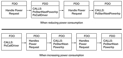
NTSTATUS OnPowerIrp(PDEVICE_OBJECT pDevObj, PIRP pIrp) { NTSTATUS status; PIO_STACK_LOCATION stack = IoGetCurrentIrpStackLocation( pIrp ); PDEVICE_EXTENSION pDevExt = (PDEVICE_EXTENSION) pDevObj -> DeviceExtension; ULONG subCode = stack->MinorFunction; switch (subCode) { ... case IRP_MN_SET_POWER: POWER_STATE_TYPE type = stack->Parameters.Power.Type; if (type != DevicePowerState) // System power state change notification // Driver can prepare for eventual device // power change - sent later ForwardPowerIrp(pDevObj, pIrp); DEVICE_POWER_STATE newState = stack->Parameters.Power.State; if (newState < pDevExt->currentPowerState) { // Request to raise power - tell PDO first. // Set a completion routine so that we can // regain control after lower-level finishes IoCopyCurrentIrpStackLocationToNext( pIrp ); IoSetCompletionRoutine( pIrp, PowerUpFinish, NULL, TRUE, TRUE, TRUE); PoCallDriver( pDevExt->LowerDriver, pIrp ); Return STATUS_PENDING; } else { // request to reduce power - do it first. // Perform device-specific power-up ops. // Tell Power Mgr device has changed state PoSetPowerState( pDevObj, type, newState); // Tell Power Mgr OK to send this level // another Power IRP PoStartNextPowerIrp( pIrp ); // And pass the Power IRP down... return PoCallDriver( pDevExt->LowerDriver, pIrp ); } break; ... NTSTATUS PowerUpFinish( PDEVICE_OBJECT pDevObj, PIRP pIrp, PVOID pContext) { PIO_STACK_LOCATION stack = IoGetCurrentIrpStackLocation( pIrp ); PDEVICE_EXTENSION pDevExt = (PDEVICE_EXTENSION) pDevObj -> DeviceExtension; DEVICE_POWER_STATE newState = stack->Parameters.Power.State; // Perform device-specific power-up now that the bus // has supplied the device with power // Inform the Power Mgr of the state change PoSetPowerState( pDevObj, DevicePowerState, newState); // And signal an OK for more Power IRPs PoStartNextPowerIrp( pIrp ); return STATUS_SUCCESS; }
|
EAN: 2147483647
Pages: 156