8.2 Call Flow Design
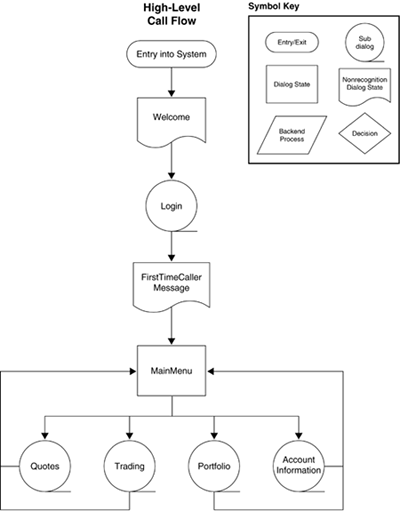
| When you design the call flow, you must think through all the design strategies in complete detail: how the caller will navigate through the system, how menus will be structured, how information will be presented to the caller, where NVA will be played, where other systems will be integrated, how failure modes will be dealt with, and so on. Chapters 8 13 have extensive coverage of design guidelines and specific dialog strategies. Figure 8-1 shows an example of a high-level call flow diagram for the Lexington Brokerage application (Chapter 14 shows, in detail, the development of call flows for this application). The example shows several types of states. The Main Menu state is a dialog state of the type defined in section 8.1. It consists of a prompt, a grammar, error and universal handling, and, depending on what was recognized, transitions to a following state. Welcome and FirstTimeCallerMessage are nonrecognition states: They play messages but do not perform recognition. Login is a placeholder for a subdialog: a detailed dialog that is fleshed out in a later diagram. Following Main Menu are four subdialogs, each representing one of the four major functional areas of the application. Each of these is also a subdialog, fleshed out in later diagrams. Figure 8-1. High-level call flow diagram for the Lexington Brokerage application.
Note that you do not flesh out the wording of prompts and messages when you design the call flow. That is part of a later step, to be covered later in this chapter. The states of the call flow diagram are typically given descriptive labels so that the intended meaning of the prompts is clear. Follow these guidelines in determining the structure of your call flow diagrams:
|
