Two Types of BPDUs
To this point, the chapter has referred to all BPDUs as a single type. Actually, there are two types of BPDUs:
Configuration BPDUs
Topology Change Notification (TCN) BPDUs
Configuration BPDUs are originated by the Root Bridge and flow outward along the active paths that radiate away from the Root Bridge. Topology Change Notification BPDUs flow upstream (toward the Root Bridge) to alert the Root Bridge that the active topology has changed. The following sections discuss both of these BPDUs in detail.
Configuration BPDUs
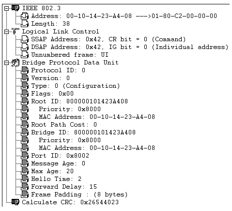
All of the BPDUs discussed so far (and the vast majority of BPDUs on a healthy network) are Configuration BPDUs. Figure 6-15 illustrates a BPDU's protocol format.
Figure 6-15. Configuration BPDU Decode
Note
For simplicity, the chapter has so far ignored the fact that there are two types of BPDUs and simply has used the term BPDU. However, recognize that all of these cases were referring to Configuration BPDUs. The second type of BPDU, the Topology Change BPDU, is discussed in the next section.
The decode in Figure 6-15 was captured and displayed by the NetXRay software from Network Associates (formerly Network General). Although considerably newer versions are available for sale, the version shown in Figure 6-15 is useful because it provides a very easy-to-read representation and decode of the Spanning-Tree Protocol. At the top of the screen you can observe the Ethernet 802.3 header. The source address is the MAC address of the individual port sending the BPDU. Every port on a Catalyst uses a unique Source MAC Address value for BPDUs sent out that port. Note the difference between this MAC address and the MAC address used to create the BID. The source MAC address is different on every Catalyst port. The BID is a global, box-wide value (within a single VLAN) that is formed from a MAC address located on the supervisor card or backplane. The source MAC is used to build the frame that carries the BPDU, whereas the BID's MAC is contained within the actual Configuration BPDU.
The Destination MAC Address uses the well-known STP multicast address of 01-80-C2-00-00-00. The Length field contains the length of the 802.2 LLC (Logical Link Control) header, BPDU, and pad that follows. Note that the CRC shown at the bottom of the screen is also part of the 802.3 encapsulation (specifically, the 802.3 trailer).
Below the 802.3 header lies the 802.2 LLC header. This 3-byte header consists of three fields that essentially identify the payload (in this case, a BPDU). The IEEE has reserved the DSAP (destination service access point) and SSAP (source service access point) value 0x42 hex to signify STP. This value has the unique advantage of being the same regardless of bit ordering (0x42 equals 0100 0010 in binary), avoiding confusion in environments that use translational bridging. Don't worry about the next byte, the control byte. It turns out that every non-SNA protocol you can name (including STP) always uses the value 0x03 to represent an Unnumbered Information (UI) frame.
The lower two-thirds of the output contains the actual BPDU. Configuration BPDUs consist of the following 12 fields (although many displays break the two BIDs out into separate subfields as shown in Figure 6-15):
Protocol ID Always 0. Future enhancements to the protocol might cause the Protocol ID values to increase.
Version Always 0. Future enhancements to the protocol might cause the Version value to increase.
Type Determines which of the two BPDU formats this frame contains (Configuration BPDU or TCN BPDU). See the next section, "Topology Change Notification BPDUs," for more detail.
Flags Used to handle changes in the active topology and is covered in the next section on Topology Change Notifications.
Root BID (Root ID in Figure 6-15) Contains the Bridge ID of the Root Bridge. After convergence, all Configuration BPDUs in the bridged network should contain the same value for this field (for a single VLAN). NetXRay breaks out the two BID subfields: Bridge Priority and bridge MAC address. See the "Step One: Elect One Root Bridge" section for more detail.
Root Path Cost The cumulative cost of all links leading to the Root Bridge. See the earlier "Path Cost" section for more detail.
Sender BID (Bridge ID in Figure 6-15) The BID of the bridge that created the current BPDU. This field is the same for all BPDUs sent by a single switch (for a single VLAN), but it differs between switches. See the "Step Three: Elect Designated Ports" section for more detail.
Port ID Contains a unique value for every port. Port 1/1 contains the value 0x8001, whereas Port 1/2 contains 0x8002 (although the numbers are grouped into blocks based on slot numbers and are not consecutive). See the "Load Balancing" section of Chapter 7 for more detail.
Message Age Records the time since the Root Bridge originally generated the information that the current BPDU is derived from. If a bridge looses connectivity to the Root Bridge (and hence, stops receiving BPDU refreshes), it needs to increment this counter in any BPDUs it sends to signify that the data is old. Encoded in 256ths of a second.
Max Age Maximum time that a BPDU is saved. Also influences the bridge table aging timer during the Topology Change Notification process (discussed later). See the "Three STP Timers" section for more detail. Encoded in 256ths of a second.
Hello Time Time between periodic Configuration BPDUs. The Root Bridge sends a Configuration BPDU on every active port every Hello Time seconds. This causes the other bridges to propagate BPDUs throughout the bridged network. See the "Three STP Timers" section for more detail. Encoded in 256ths of a second.
Forward Delay The time spent in the Listening and Learning states. Also influences timers during the Topology Change Notification process (discussed later). See the "Three STP Timers" section for more detail. Encoded in 256ths of a second.
Table 6-6 summarizes the Configuration BPDU fields.
Table 6-6. Configuration BPDU Fields
Field
Octets
Use
Protocol ID
2
Always 0
Version
1
Always 0
Type
1
Type of current BPDU
0 = Configuration BPDU
Flags
1
LSB = Topology Change (TC) flag
MSB = Topology Change Acknowledgment (TCA) flag
Root BID
8
Bridge ID of current Root Bridge
Root Path Cost
4
Cumulative cost to Root Bridge
Sender BID
8
Bridge ID of current bridge
Port ID
2
Unique ID for port that sent this BPDU
Message Age
2
Time since Root Bridge-created BPDU used to derive current BPDU
Max Age
2
Period to save BPDU information
Hello Time
2
Period between BPDUs
Forward Delay
2
Time spent in Listening and Learning states
Topology Change Notification BPDUs
Although the majority of BPDUs on a healthy network should be Configuration BPDUs, all bridged networks see at least a few of the second type of BPDU, the Topology Change Notification (TCN) BPDU. TCN BPDUs, as their name suggests, play a key role in handling changes in the active topology. Figure 6-16 illustrates a decode of a TCN BPDU.
Figure 6-16. Topology Change Notification BPDU Decode
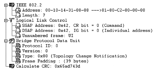
The TCN BPDU is much simpler than the Configuration BPDU illustrated in Figure 6-15 and consists of only three fields. TCN BPDUs are identical to the first three fields of a Configuration BPDU with the exception of a single bit in the Type field. After all, at least one bit is needed to say "this is a TCN BPDU, not a Configuration BPDU." Therefore, the Type field can contain one of two values:
0x00 (Binary: 0000 0000) Configuration BPDU
0x80 (Binary: 1000 0000) Topology Change Notification (TCN) BPDU
That's it. TCN BPDUs don't carry any additional information.
EAN: N/A
Pages: 223
- Chapter II Information Search on the Internet: A Causal Model
- Chapter VIII Personalization Systems and Their Deployment as Web Site Interface Design Decisions
- Chapter X Converting Browsers to Buyers: Key Considerations in Designing Business-to-Consumer Web Sites
- Chapter XIII Shopping Agent Web Sites: A Comparative Shopping Environment
- Chapter XVI Turning Web Surfers into Loyal Customers: Cognitive Lock-In Through Interface Design and Web Site Usability