Catalyst VLAN Configuration
Some VLAN components assign stations to VLANs based upon MAC addresses. The Catalyst, on the other hand, associates ports to a VLAN. Any device attached to the port belongs to the VLAN describing the switch interface. Even if a shared hub attaches to the port, all stations on the hub belong to the same VLAN. This is called a port-centric approach to VLANs. To configure VLANs in a Catalyst, you must first plan the VLAN membership and then assign ports to the correct VLAN. Planning VLAN membership involves knowing what Layer 3 networks should belong to the VLAN, what inter-VLAN connectivity you require, and where the VLAN will be distributed. Are you going to use end-to-end VLANs or use a Layer 3 approach to deploy your networks? After you proceed through the planning stages, you are ready to create the VLANs.
Planning VLANs
Before you enable new VLANs, make sure that you know what you really want to do and how your actions can affect other VLANs or stations already present in your system. The planning at this stage can primarily focus around Layer 3 issues. What networks need to be supported in the VLAN? Is there more than one protocol that you want in the VLAN? Because each VLAN corresponds to a broadcast domain, you can support multiple protocols in the VLAN. However, you should only have one network for each protocol in the VLAN.
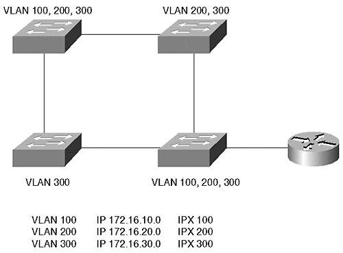
A multiswitch system like that shown in Figure 5-16 can have several VLANs.
Figure 5-16. A Typical VLAN Network Address Deployment

Each VLAN in Figure 5-16 supports multiple protocols. For the networks to communicate with each other, they must pass through a router. The router on a stick in Figure 5-16 interconnects several networks together. Example 5-1 shows a configuration file for this router.
Example 5-1 Router on a Stick Configuration File
interface fastethernet 2/0.1 ip address 172.16.10.1 255.255.255.0 ipx network 100 encapsulation isl 100 interface fastethernet 2/0.2 ip address 172.16.20.1 255.255.255.0 ipx network 200 encapsulation isl 200 interface fastethernet 2/0.3 ip address 172.16.30.1 255.255.255.0 encapsulation isl 300
Example 5-1 sets up a trunk between a device and the router. Trunks and Inter-Switch Link (ISL) encapsulation are discussed in more detail in Chapter 8. Trunks allow traffic from more than one VLAN to communicate over one physical link. The encapsulation isl command in Example 5-1 instructs the router to use ISL trunking to communicate with the broadcast domain for each subinterface. Note that the router configuration uses subinterfaces. Normally, in a router, you assign a single address per protocol on an interface. However, when you want to use a single physical interface in a way that, to the routing protocols, appears as multiple interfaces, you can use subinterfaces for example, when creating a trunk between a Catalyst and a router, as in Example 5-1. The router needs to identify a separate broadcast domain for each VLAN on the trunk.
Cisco routers use a concept of subinterfaces to spoof the router into thinking that a physical interface is actually more than one physical interface. Each subinterface identifies a new broadcast domain on the physical interface and can belong to its own IP network, even though they all actually belong to the same major interface. The router configured in Example 5-1 uses three subinterfaces making the router think that the one physical interface (the major interface) interface fastethernet 2/0 is actually three physical interfaces, and therefore, three broadcast domains. Each belongs to a different IP subnet. You can recognize a subinterface on a Cisco router because the major interface designator has a .x after it. For example, subinterface 3 is identified in Example 5-1 as int fastethernet 2/0.3 where .3 designates the specific subinterface for the major interface.
The subinterface concept arises again when configuring LANE and MPOA on routers and on the Catalyst ATM modules.
In Example 5-1, which network is isolated from the others? IPX network 300 is isolated because the router does not have this network defined on any of its interfaces.
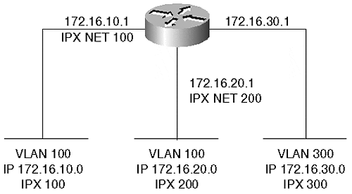
At times, a physical network configuration can confuse you. A common question we hear in class or consulting situations is, "Can I do this with a VLAN?" Frequently, an answer can be devised by representing the VLANs in a logical configuration. Figure 5-16 shows a physical network; Figure 5-17 shows the same network, but redrawn to show the logical connectivity. The drawing replaces each VLAN with a wire representation labeled with the networks assigned to the VLAN. This more conventional representation helps when trying to design and deploy a VLAN, because it places networks and components into their logical relationship.
Figure 5-17. A Logical Representation of Figure 5-16

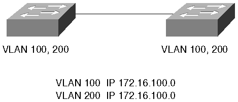
Figure 5-18 shows another network configuration where two VLANs carry the same IP network. Nothing prevents this configuration and it is valid. It is not, however, recommended for most networks. This configuration represents the same subnet on two logical wires.
Figure 5-18. Overlapping IP Networks

The network could be redrawn as in Figure 5-19 where clearly there are two isolated broadcast domains. As long as you do not attempt to interconnect them with a router, this configuration is completely valid. Why can they not be connected with a router? Because this forces a router to have two interfaces that belong to the same IP subnetwork. The router does not let you do this.
Figure 5-19. Logical Representation of Figure 5-18

The logical connectivity drawing loses information regarding physical interconnectivity which is important for bandwidth planning. For example, Figure 5-19 might lead you to believe that all devices in VLAN 100 have full bandwidth available between all components. You might also believe the same regarding VLAN 200. However, the physical representation of Figure 5-18 makes it clear that the two VLANs share a link between the switches. This must be a shared bandwidth link which is not obvious from the logical representation.
Tip
Use the logical representation to plan and troubleshoot Layer 3 issues and use the physical drawings to determine Layer 2-related issues.
Creating VLANs
Creating a VLAN involves the following steps:
Assign the Catalyst to a VTP domain
Create the VLAN
Associate ports to a VLAN
To facilitate creation, deletion, and management of VLANs in Catalysts, Cisco developed a protocol called VLAN Trunking Protocol (VTP). Chapter 12, "VLAN Trunking Protocol," covers VTP in more detail. However, a brief introduction is necessary here. You can divide a large Catalyst network into VTP management domains to ease some configuration and management tasks. Management domains are loosely analogous to autonomous systems in a routed network where a group of devices share some common attributes. Catalysts share VLAN information with each other within a VTP domain. A Catalyst must belong to a VTP domain before you can create a VLAN. You cannot create a VLAN on any Catalyst. The Catalyst must be configured in either the server or transparent mode to create the VLAN. By default, the Catalyst operates in the server mode. These modes and the command details to set them are described in Chapter 12.
You can configure a Catalyst's VTP domain membership with the set vtp domain name command. Each domain is uniquely identified by a text string. Note that the name is case sensitive. Therefore, a domain name of Cisco is not the same as cisco. Other rules about VTP domains that you need to consider are also detailed in Chapter 12.
Whenever you create or delete a VLAN, VTP transmits the VLAN status to the other Catalysts in the VTP domain. If the receiving Catalyst in the VTP domain is configured as a server or client, it uses this information to automatically modify its VLAN list. This saves you the task of repeating the command to create the same VLAN in all participating Catalysts within the domain. Create the VLAN in one Catalyst, and all Catalysts in the domain automatically learn about the new VLAN. The exception to the rule occurs if the receiving Catalyst is in transparent mode. In this case, the receiving Catalyst ignores the VTP. Transparent Catalysts only use locally configured information.
After the Catalyst belongs to a named VTP domain, you can create a VLAN. Use the set vlan command to create a VLAN in a Catalyst.
Example 5-2 shows three attempts to create VLAN 2. Note that in the second attempt the Catalyst fails to create the VLAN as indicated in the bolded line of the output. It fails because the Catalyst was not assigned to a VTP management domain. Only after the Catalyst is assigned to a VTP domain is Catalyst able to create the VLAN. What is the domain name that the Catalyst belongs to? The Catalyst belongs to the VTP domain wally.
Example 5-2 set vlan Screen Example
Console> (enable) set vlan 2 willitwork Usage: set vlan <vlan_num> [name <name>] [type <type>] [state <state>] [said <said>] [mtu <mtu>] [ring <ring_number>] [bridge <bridge_number>] [parent <vlan_num>] [mode <bridge_mode>] [stp <stp_type>] [translation <vlan_num>] [backupcrf <off|on>] [aremaxhop <hopcount>] [stemaxhop <hopcount>] (name = 1..32 characters, state = (active, suspend) type = (ethernet, fddi, fddinet, trcrf, trbrf) said = 1..4294967294, mtu = 576..18190, ring_number = 0x1..0xfff bridge_number = 0x1..0xf, parent = 2..1005, mode = (srt, srb) stp = (ieee, ibm, auto), translation = 1..1005 hopcount = 1..13) Console> (enable) set vlan 2 name willitwork Cannot add/modify VLANs on a VTP server without a domain name. Console> (enable) Console> (enable) set vtp domain wally VTP domain wally modified Console> (enable) set vlan 2 willitwork Vlan 2 configuration successful Console> (enable)
Note that the usage information indicates that the minimum input necessary to create a VLAN is the VLAN number. Optionally, you can specify a VLAN name, type, and other parameters. Many of the other parameters configure the Catalyst for Token Ring or FDDI VLANs. If you do not specify a VLAN name, the Catalyst assigns the name VLAN#. If you do not specify a VLAN type, the Catalyst assumes that you are configuring an Ethernet VLAN. Assigning a name does not change the performance of the Catalyst or VLAN. If used well, it enables you to document the VLAN by reminding yourself what the VLAN is for. Use meaningful names to document the VLAN. This helps you with troubleshooting and configuration tasks.
After you create a VLAN, you can assign ports to the VLAN. Assigning ports to a VLAN uses the same command as for creating the VLAN. Example 5-3 shows an attempt to assign a block of ports to VLAN 2. Unfortunately, the command is entered incorrectly the first time. What is wrong with the command? The set vlan command fails in the first case because the range specifies a non-existent interface on the Supervisor module. 1/8 indicates the eighth port on the Supervisor.
Example 5-3 Assigning Ports to a VLAN
Console> (enable) set vlan 2 2/1-1/8 Usage: set vlan <vlan_num> <mod/ports…> (An example of mod/ports is 1/1,2/1-12,3/1-2,4/1-12) Console> (enable) set vlan 2 2/1-2/8 VLAN 2 modified. VLAN 1 modified. VLAN Mod/Ports ---- ----------------------- 2 2/1-8 Console> (enable)
After the port designation is corrected, the Catalyst successfully reassigns the block of ports to VLAN 2. When designating ports, remember that you can assign a block by using hyphens and commas. Do not insert any spaces, though, between the ports on the line. This causes the Catalyst to parse the command leaving you with only some of the ports assigned into the VLAN.
Note
In many instances where administrators install Catalysts, legacy hubs already exist. You might have network areas where stations do not need the dedicated bandwidth of a switch port and can easily share bandwidth with other devices. To provide more bandwidth, you can elect to not attach as many devices as were originally attached, and then attach the hub to a Catalyst interface. Be sure to remember, though, that all of the devices on that hub belong to the same Layer 2 VLAN because they all ultimately attach to the same Catalyst port.
Deleting VLANs
You can remove VLANs from the management domain using the clear vlan vlan_number command. For example, if you want to remove VLAN 5 from your VTP management domain, you can type the command clear vlan 5 on a Catalyst configured as a VTP server. You cannot delete VLANs from a VTP client Catalyst. If the Catalyst is configured in transparent mode, you can delete the VLAN. However, the VLAN is removed only from the one Catalyst and is not deleted throughout the management domain. All VLAN creations and deletions are only locally significant on a transparent Catalyst.
When you attempt to delete the VLAN, the Catalyst warns you that all ports belonging to the VLAN in the management domain will move into a disabled state. If you have 50 devices as members of the VLAN when you delete it, all 50 stations become isolated because their local Catalyst port becomes disabled. If you recreate the VLAN, the ports become active again because the Catalyst remembers what VLAN you want the port to belong to. If the VLAN exists, the ports become active. If the VLAN does not exist, the ports become inactive. This could be catastrophic if you accidentally eliminate a VLAN that still has active users on it.
Also, realize that if you have a VTP management domain where you have most of your Catalysts configured as VTP servers and clients with a few Catalysts configured in transparent mode, you can inadvertently cause another situation when you delete a VLAN in the transparent device when the VLAN exists throughout the management domain. For example, suppose you have three Catalysts in a row with Cat-A configured in server mode, Cat-B configured in transparent mode, and Cat-C configured in client or server mode. Each Catalyst has a member of VLAN 10, so you create the VLAN on Cat-B, and you create it on Cat-A (Cat-C acquires the VLAN information from Cat-A as a result of VTP). From a Spanning Tree point of view, you have one Spanning Tree domain, and therefore, one Spanning Tree Root Bridge. But suppose that you decide you no longer need VLAN 10 on Cat-B, because there are no longer members of the VLAN. So, you delete the VLAN with the clear vlan 10 command. From a VLAN point of view, this is perfectly acceptable. However, from a Spanning Tree point of view, you now created two Spanning Tree domains. Because Cat-B no longer participates in the VLAN, it no longer contributes to the Spanning Tree for that VLAN. Therefore, Cat-A and Cat-C each become a Root Bridge for VLAN 10 in each of their Spanning Tree domains.
Although Spanning Tree reconverges as a result of the apparent topology change, users in VLAN 10 cannot communicate with each other until the Spanning Tree topology finally places ports into the forwarding state.
Tip
When deleting VLANs from a management domain, whether it is on a Catalyst configured in server or transparent mode, be sure that you consider how you can affect the network. You have the possibility of isolating a lot of users and of disrupting Spanning Tree in a network.
Viewing VLAN Configurations
Of course, you want to examine your VLAN configurations at one time or another. Example 5-4 shows a Catalyst output for the show vlan command.
Example 5-4 show vlan Command and Output
Console> (enable) show vlan VLAN Name Status Mod/Ports, Vlans ---- -------------------------------- --------- ---------------------------- 1 default active 1/1-2 2/9-24 2 willitwork active 2/1-8 1002 fddi-default active 1003 token-ring-default active 1004 fddinet-default active 1005 trnet-default active VLAN Type SAID MTU Parent RingNo BrdgNo Stp BrdgMode Trans1 Trans2 ---- ----- ---------- ----- ------ ------ ------ ---- -------- ------ ------ 1 enet 100001 1500 - - - - - 0 0 2 enet 100002 1500 - - - - - 0 0 1002 fddi 101002 1500 - 0x0 - - - 0 0 1003 trcrf 101003 1500 0 0x0 - - - 0 0 1004 fdnet 101004 1500 - - 0x0 ieee - 0 0 1005 trbrf 101005 1500 - - 0x0 ibm - 0 0 VLAN AREHops STEHops Backup CRF ---- ------- ------- ---------- 1003 7 7 off Console> (enable)
VLAN 2, created in the previous section, is highlighted in the output of Example 5-4. The show vlan output is divided into three portions. The first portion shows the VLAN number, name, status, and ports assigned to the VLAN. This provides a quick evaluation of the condition of a VLAN within the Catalyst. The second portion displays the VLAN type and other parameters relevant to the VLAN for example, the MTU size. The other columns display information for Token Ring and FDDI VLANs. The third portion of the output displays further information for source-routed VLANs.
Note that there are several VLANs present in the output. All of the entries in the display, except for VLAN 2, show default VLANs which are always present in the Catalyst. These default VLANs cannot be removed from the Catalyst. When you first power a new Catalyst, all Ethernet interfaces belong to VLAN 1. Also, the Supervisor module sc0 or sl0 interface belongs to this VLAN by default. If you interconnect several Catalysts, each populated with Ethernet modules and with only default configurations, all of the Catalyst interfaces belong to the same VLAN. You have one giant broadcast domain.
EAN: N/A
Pages: 223