Integration between Routing and Bridging
The section "MLS versus 8500s" discussed the advantages of having Layer 3 barriers or partitions in your network (this issue is also discussed extensively in Chapters 14, 15, and 17). However, for a variety of reasons, many people want to avoid the "hard barriers" formed by this approach. Instead, they seek "softer barriers" where some protocols or VLANs are terminated while others pass through. This requires a mixture of routing (that is, Layer 3 switching) and bridging (that is, Layer 2 switching). The next two sections look at the two most common forms of mixing routing and bridging.
Note
A third technique is possible using the Catalyst 6000 Native IOS Mode. This will be discussed in Chapter 18.
Bridging between VLANs
One of the simplest ways of avoiding the "hardness" of a Layer 3 barrier is bridging between multiple VLANs. Many network designers want to do this when they have two separate VLANs that need to share some non-routable protocol such as local-area transport (LAT) or NetBIOS/NetBEUI.
Tip
Other network designers cringe at this thought because it no longer keeps the VLANs separate.
This sort of bridging can be easily configured using the same bridge-group technology that Cisco routers have supported for many years. For example, the configuration in Example 11-24 enables bridging between VLANs 2 and 3 on an 8500.
Example 11-24 Using Bridge Groups to Bridge between VLANs
interface FastEthernet0/0/0 no ip address ! interface FastEthernet0/0/0.1 encapsulation isl 1 ip address 10.1.1.1 255.255.255.0 ! interface FastEthernet0/0/0.2 encapsulation isl 2 ip address 10.1.2.1 255.255.255.0 ipx network 2 bridge-group 1 ! interface FastEthernet0/0/0.3 encapsulation isl 3 ip address 10.1.3.1 255.255.255.0 ipx network 3 bridge-group 1 ! interface FastEthernet0/0/0.4 encapsulation isl 4 ip address 10.1.4.1 255.255.255.0 ipx network 4 ! bridge 1 protocol ieee
The configuration in Example 11-24 results in IP and IPX traffic being routed between subinterfaces Fast Ethernet1/0.2 and 1/0.3 while all other protocols are bridged. No bridging is performed on subinterfaces Fast Ethernet1/0.1 and 1/0.4. Notice that this requires IP users in VLANs 2 and 3 to use different IP subnets (and IPX networks) but the same AppleTalk cable range.
Tip
When using bridge-groups, remember that protocols configured with a Layer 3 address will be routed while all other protocols will be bridged. For example, if you only configure an IP address on a given interface, IP will be routed and all other protocols (IPX, AppleTalk, DECnet, and so on) will be bridged.
This technique is applicable as long as a particular protocol is either bridged or routed on a specific device. For instance, the previous example routed IP and IPX on every interface. Also, AppleTalk was only bridged on this device. Normal bridge-group processing does not allow you to bridge IP between two interfaces and route it between two other interfaces. To do so requires a feature called Integrated Routing and Bridging (IRB).
IRB
Integrated Routing and Bridging (IRB) is a technique Cisco introduced in IOS 11.2 to allow a single protocol to be both bridged and routed on the same box. IOS 11.1 introduced a precursor to IRB called Concurrent Routing and Bridging (CRB). This allowed a particular protocol such as IP to be both bridged and routed on the same device. It allowed all of the routed interfaces using this protocol to communicate and all of the bridged interfaces to communicate. However, CRB did not let routed interfaces communicate with the bridged interfaces. In other words, the routed and bridged worlds for the configured protocol were treated as two separate islands. Most people were not looking for this functionality.
IRB filled this gap by allowing communication between these two islands. This enabled configurations such as those shown in Figure 11-28.
Figure 11-28. A Sample IRB Configuration
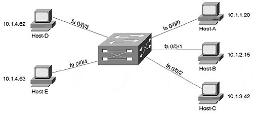
The interfaces on the right side of the router (fa0/0/0, fa0/0/1, and fa0/0/2) all use IP addresses on separate IP subnets. Conversely, the interfaces on the left (fa0/0/3 and fa0/0/4) both fall on the same subnet. And, because IRB is in use, 10.1.4.62 could ping 10.1.1.20 (this is not possible in CRB).
To create a link between the routed and bridged domains, Cisco created a special virtual interface known as a Bridged Virtual Interface (BVI). The BVI can be configured with Layer 3 addresses (it cannot be configured with bridging statements) and acts as a routed interface into the rest of the box. For example, the BVI in Figure 11-28 might use an IP address of 10.1.4.1, as illustrated in Figure 11-29.
Figure 11-29. A Logical Representation of a BVI
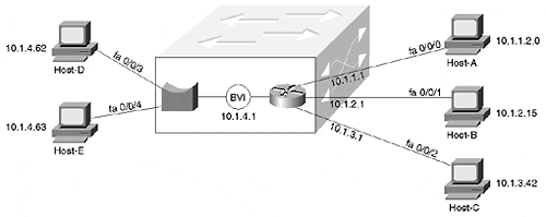
If interface fa0/0/4 receives a frame with Host-D's MAC address, it bridges it out interface fa0/0/3. However, if Host-D pings Host-A, Host-D sends the IP packet to its default gateway, address 10.1.4.1 (the BVI's address). If necessary, Host-D ARPs for 10.1.4.1 to learn the BVI's MAC address. When interface fa0/0/4 receives the traffic with a MAC address that belongs to the BVI, it knows to route, not bridge, the traffic. The normal routing process then sends the traffic out interface fa0/0/0.
The BVI essentially acts as a single routed interface on behalf of all of the bridged interfaces in a particular VLAN. In Figure 11-29, the BVI communicates with the right side of the box through routing, whereas the left side uses bridging.
Tip
You need one BVI interface for each VLAN that contains two or more interfaces on a single IOS-based router (except for the ports that make up an individual EtherChannel bundle).
Example 11-25 shows sample configuration for the network illustrated in Figures 11-28 and 11-29.
Example 11-25 IRB Configuration
interface FastEthernet0/0/0 ip address 10.1.1.1 255.255.255.0 ! interface FastEthernet0/0/1 ip address 10.1.2.1 255.255.255.0 ! interface FastEthernet0/0/2 ip address 10.1.3.1 255.255.255.0 ! interface FastEthernet0/0/3 no ip address bridge-group 1 ! interface FastEthernet0/0/4 no ip address brige-group 1 ! interface BVI 1 ip address 10.1.4.1 255.255.255.0 ! bridge 1 protocol ieee bridge 1 protocol ieee bridge 1 route ip
Tip
The BVI interface number must match the bridge group number.
IRB is an important feature on platforms such as the Catalyst 8500. For instance, consider the case where you want to directly connect 10 servers to an 8540 along with 20 trunks that lead to separate wiring closet switches. Assume the servers are going to all be placed in the same subnet (therefore bridging IP traffic), whereas each wiring closet switch uses a separate subnet (therefore routing IP). Without IRB, it is not possible to both route and bridge the IP traffic in one device. In other words, IRB allows you to route IP subnets while also extending the server farm VLAN through the router. Another advantage to IRB is that it is performed at nearly wire speed in the 8500 (IRB is Fast-Switched in software-based routers).
However, IRB does have its downsides. Most importantly, the extensive use of IRB can create configuration nightmares. For example, consider an 8540 with 100+ interfaces and 30 or 40 BVIs (one for every VLAN that needs to mix routing and bridging). Also, it can quickly deplete the number of available logical interfaces supported by the IOS. To avoid these issues, IRB should be used to solve specific and narrowly defined problems. Do not try to build your entire network on IRB.
Tip
A single BVI that contains many interfaces does not present configuration challenges. However, a design that uses many BVIs can lead to problems and confusion.
Issues and Caveats with Bridging between VLANs
Regardless of which approach is used, bridging between VLANs can create a wide variety of problems. One of the most common problems is that of throughput and switching speed. Many organizations have used software-based routers to rely on bridge groups and possibly BVIs to allow non-routable traffic to cross VLAN boundaries. However, software-based bridges perform these bridging functions at IOS Fast-Switching speeds. This creates a situation where traffic gets Layer 2 switched at millions of packets per second only to slam into a software-based bridging process often running at less than 100,000 pps. Talk about having the Autobahn suddenly turn into a dirt road!
Note
As discussed earlier, switching router platforms such as the 8500s do not suffer from this drawback because they perform both Layer 2 and Layer 3 forwarding at essentially the same speed.
However, even if the throughput problem is not an issue in your network, there is another problem that can surface. Assume that you link two Layer 2 domains with the configuration in Example 11-26.
Example 11-26 Routing IP and IPX While Bridging All Other Protocols
interface FastEthernet0/0/0 no ip address ! interface FastEthernet0/0/0.1 encapsulation isl 1 ip address 10.1.1.1 255.255.255.0 ipx network 1 bridge-group 1 ! interface FastEthernet0/0/0.2 encapsulation isl 2 ip address 10.1.2.1 255.255.255.0 ipx network 2 bridge-group 1 ! bridge 1 protocol ieee
The configuration in Example 11-26 routes IP and IPX between VLANs 1 and 2 but also allows non-routable traffic such as NetBIOS/NetBEUI to be bridged through the router. However, this also merges the Spanning Trees in VLAN 1 and 2. This introduces two significant problems:
Scalability problems When two (or more) Spanning Trees are merged into a single tree, all of the Spanning Tree scalability benefits created by introducing routers disappear. A single Root Bridge is established between both VLANs. A single set of least-cost paths is found to this Root Bridge. Spanning Tree instability can easily and quickly spread throughout both VLANs and create network-wide outages.
Defeats Spanning Tree load balancing Recall from Chapter 7 that Spanning Tree load balancing uses multiple VLANs to create different logical topologies between VLANs. For example, VLAN 1 can use Trunk-1 and VLAN 2 can use Trunk-2. However, if the Spanning Trees are merged because of inter-VLAN bridging, both VLANs are forced to use a single trunk. This cuts your available bandwidth in half!
Even if you find a way to avoid the issues previously discussed, you must plan very carefully to avoid a third problem that I refer to as the Broken Subnet Problem. Figure 11-30 illustrates this issue.
Figure 11-30. The Broken Subnet Problem
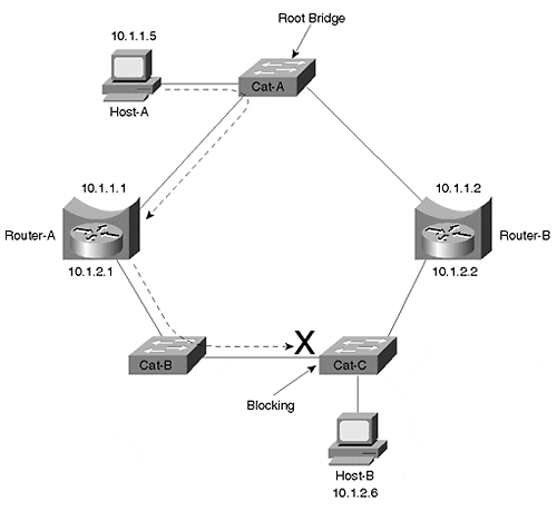
Three Layer 2 Catalysts and two routers have been used to form a ring. Router-A and Router-B have been configured to route IP and bridge all other protocols using a bridge-group 1 command on both Ethernet interfaces. As a result, IP sees the topology shown in Figure 11-31.
Figure 11-31. IP's View of the Network Shown in Figure 11-30
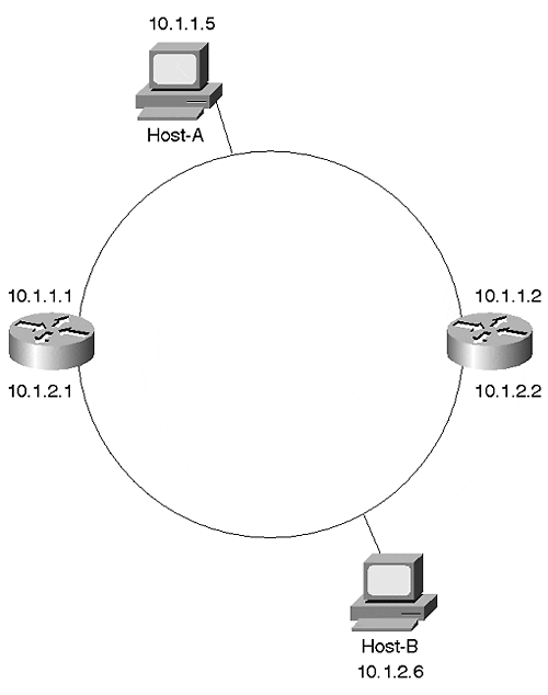
In other words, IP has divided the network into two subnets. However, the Spanning-Tree Protocol has a very different view of the world. Spanning Tree knows nothing about IP's interpretation. Instead, it sees only a ring of five Layer 2 devices. Assuming that Cat-A becomes the Root Bridge, Spanning Tree creates the topology shown in Figure 11-32 (see Chapter 6 for information on DP, RP, F, and B).
Figure 11-32. Spanning Tree's View of the Network Shown in Figure 11-29
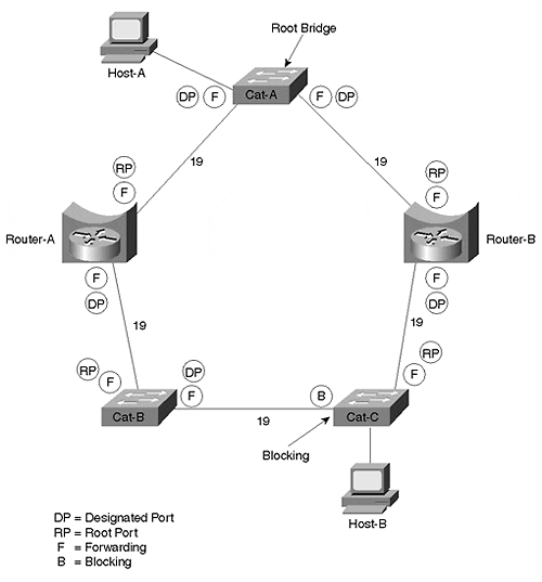
Unfortunately, this can create a very subtle problem. Consider what happens if Host-A tries to send IP data to Host-B. Host-A recognizes that Host-B is in a different subnet and forwards the traffic to Router-A, its default gateway. Router-A does the normal IP routing thing and forwards the traffic out its interface E1. However, the traffic cannot be delivered to Host-B because the Layer 2 switches have blocked the path (remember that Spanning Tree blocks all traffic on a Catalyst, not just non-routable traffic)! The dashed line in Figure 11-30 shows this path.
The Broken Subnet Problem can be extremely difficult to troubleshoot and diagnose. In many cases, only a very small number of nodes experience problems communicating with each other. For example, Host-A cannot reach Host-B, but it might be able to reach every other address in the network. If your network has Spanning Tree stability problems, the broken link is constantly shifting locations. Furthermore, the failure is protocol specific. If Host-A tries to reach Host-B using any protocol other than IP, it succeeds. All of these issues can lead to many extremely long days of troubleshooting before the actual problem is discovered.
How to Fix the Broken Subnet Problem
In general, there are three ways to fix the Broken Subnet Problem:
Disable the inter-VLAN bridging on at least one bridge.
Manipulate the Spanning Tree parameters to move the Blocking port to one of the router ports.
Run a different version of the Spanning-Tree Protocol on the routers than on the Layer 2 switches.
Disable Inter-VLAN Bridging
The simplest and most effective solution to the Broken Subnet Problem is to disable inter-VLAN bridging on at least one of the routers (by removing the bridge-group commands from the interfaces). Because this creates a loop-free Layer 2 configuration, it prevents any of the ports in Figure 11-30 from Blocking. However, it also removes redundancy from the inter-VLAN bridging and, therefore, might not be appropriate for all networks.
Manipulating Spanning Tree Parameters
By tuning a variety of Spanning Tree parameters, the blocked port can be moved to one of the ports on the router. By doing so, the router can have full access to the network for routable protocols but also prevent Layer 2 loops within the non-routable protocols. In short, this allows the router to create a protocol-specific Blocking port. For routable protocols, the Spanning Tree Blocking port is ignored. However, for protocols the router does not route, the Blocking port is enforced. In general, there are three options for moving the Blocking port (see Table 11-1).
Table 11-1. Moving the Spanning Tree Blocking Port to a Router
Option
Description
Path Cost
Increases or decreases the STP path cost parameter to influence the election of Designated and non-Designated Ports.
Root Bridge placement
Moves the STP Root Bridge such that the Blocking port is forced to a router interface.
Multiple Spanning Trees
Uses IEEE STP on the Layer 2 Catalysts and DEC or VLAN-Bridge on the routers. See the section "Using Different Spanning-Tree Protocols."
Figure 11-33 shows how this can be done by increasing the cost of the link between Cat-A and Router-A to 1000 (the cost actually needs to be increased on the Router, not Cat-A, because Cat-A is the Root Bridge).
Figure 11-33. Moving the Blocking Port to a Router Interface
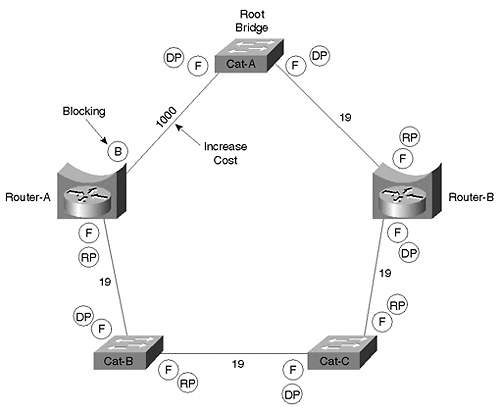
Another option is to move the Root Bridge to Router-B. When using this approach, Bridge Priorities or Path Costs might also have to be adjusted to force the Blocking port to the router-end of the link to Cat-B.
Using Different Spanning-Tree Protocols
The most complex and creative solution involves using a different version of the Spanning-Tree Protocol on the Layer 2 bridges than on the routers. Layer 2 Catalysts such as the Catalyst 6000 and Catalyst 5000 only use the IEEE version of the Spanning-Tree Protocol. Meanwhile, devices that run the full IOS, such as a 7500 router or a Catalyst 8500, can use one of three versions of the Spanning-Tree Protocol for transparent bridging (very early 8500 images only support IEEE, and VLAN-Bridge requires IOS 12.0+):
IEEE
DEC
VLAN-Bridge
As discussed in Chapter 6, Radia Perlman created the DEC version of the Spanning-Tree Protocol, which was initially offered on DEC equipment. The IEEE version was the one standardized in 802.1D. VLAN-Bridge is a Cisco-specific extension to the IEEE protocol (it uses the same BPDU layout with a SNAP header). It was created to provide exactly the sort of feature being discussed in this section.
For example, in Figure 11-30, the Catalysts Cat-A, Cat-B, and Cat-C are using the IEEE Spanning-Tree Protocol, and Router-A and Router-B are using the DEC Spanning-Tree Protocol.
At first thought, this sounds like a dangerous proposition. After all, mixing the two protocols can lead to situations where one of the protocols does not detect a loop and the whole network collapses. However, because Layer 2 Catalysts process BPDUs slightly differently than IOS routers, the results can be both safe and effective. This is possible because of the following two characteristics:
Layer 2 Catalysts flood DEC BPDUs
IOS routers swallow IEEE BPDUs if they are only running the DEC variation of the Spanning-Tree Protocol
As a result, the IEEE BPDUs are blocked by the routers, creating a topology that resembles that shown in Figure 11-34.
Figure 11-34. IEEE Topology When Running Two Versions of the Spanning-Tree Protocol
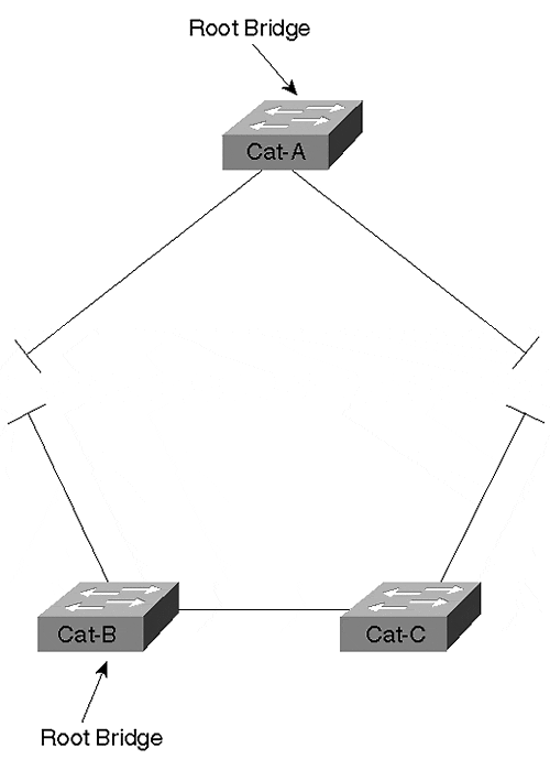
The IEEE Spanning-Tree Protocol views the network as being partitioned into two separate halves. Each half elects its own Root Bridge.
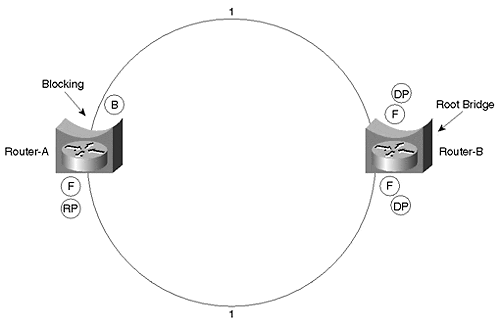
On the other hand, the DEC Spanning-Tree Protocol running on the routers sees a very different view of the network. From the DEC perspective, the Layer 2 Catalysts do not exist because DEC BPDUs are flooded without alteration by Cat-A, Cat-B, and Cat-C. This creates the logical topology diagrammed in Figure 11-35.
Figure 11-35. DEC Topology When Running Two Versions of the Spanning-Tree Protocol
Note
Notice that the DEC Spanning-Tree Protocol uses a cost of 1 for Fast Ethernet links.
As a result, the two Spanning-Tree Protocols work together to provide connectivity throughout the network. The IEEE Spanning Trees are used to make sure that Layer 2 loops are not formed between the routers. Because each IEEE Spanning Tree provides full connectivity between all of the routers it touches, this avoids the Broken Subnet Problem. The DEC protocol is then used to detect if these pockets of IEEE Spanning Tree are interconnected in a looped topology. In the case of this example, it detects that a loop has been formed and blocks a port running the DEC Spanning-Tree Protocol. Assume that Router-B is acting as the Root Bridge of the DEC Spanning Tree in Figure 11-35. This causes the upper interface on Router-A to enter the Blocking state.
Note
As a minor detail, this assumes that the upper interface on Router-B has a lower Port ID. See the "Port/VLAN Priority Load Balancing" section of Chapter 7 for more detail.
Although this can hardly be called the most intuitive approach, it can be very useful in networks that need to mix routing and bridging technology.
Tip
Use multiple versions of the Spanning-Tree Protocol to avoid the Broken Subnet Problem where the simpler techniques discussed in the previous two sections are not an option.
Recommendations on Mixing Bridging and Routing
In general, the best advice is to avoid inter-VLAN bridging wherever possible. Not only does it create the obvious problem of potentially excessive broadcast radiation, it introduces a wide variety of scalability issues.
The simplest way to avoid inter-VLAN bridging is by putting all nodes that need to communicate via non-routable protocols in a single VLAN. If this VLAN needs to span multiple switching routers in the network's core, a single BVI interface can be created without significant problems. If more than one VLAN needs to be used for non-routable traffic, strive to limit them as much as possible. Also consider migrating to routable alternatives. For example, organizations using NetBIOS/NetBEUI for Microsoft's networking features can enable WINS and use NetBIOS over TCP/IP (NBT).
Finally, remember the unique benefits provided by the combination of MLS and Catalyst-based routers such as the RSM. The Catalyst's feature-rich Layer 2 architecture makes it very easy to group various combinations of ports into multiple VLANs. The RSM's unique design that treats all of the ports in a VLAN as a single router interface (interface Vlan X) also makes it very easy to route between these VLANs. This approach is considerably simpler and more scalable (at least from a configuration standpoint) than IRB. You can obtain similar benefits by using the Native IOS Mode routing feature of the Catalyts 6000 (see Chapter 18).
EAN: N/A
Pages: 223