Choosing the Appropriate UML Diagram
UML has many diagrams—more, in fact, than you’ll probably need to know. There are at least 13 official diagrams (actually the sum varies every time we count it) and several semiofficial diagrams. Confusion can emerge because UML usually allows you to place elements from one diagram on another if the situation warrants. And the same diagram form, when used for a different purpose, could be considered a different diagram.
In Figure 1-1, we’ve constructed a UML class diagram that sums up all the major types of UML diagrams (along with their relationships), using the principle of generalization, which entails organizing items by similarities to keep the diagram compact. (See Chapter 2 for more information on generalization.)
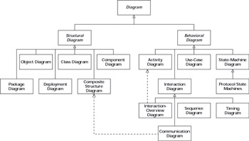
Figure 1-1: A class diagram of UML diagrams.
In Figure 1-1, the triangular arrows point from one diagram type to a more general (or more abstract) diagram type. The lower diagram type is a kind-of or sort-of the higher diagram type. Thus a Class Diagram is a kind of Structural Diagram, which is a kind of Diagram. The diagram also uses a dashed arrow to indicate a dependency—some diagrams reuse the features of others and depend on their definition. For example, the Interaction Overview Diagram depends on (or is derived from) the Activity Diagram for much of its notation. To get a line on how you might use UML diagrams, check out the summary in Table 1-1.
Slicing and dicing UML diagrams
There are many ways of organizing the UML diagrams to help you understand how you may best use them. The diagram in Figure 1-1 uses the technique of organization by generalization (moving up a hierarchy of abstraction) and specialization (moving down the same hierarchy in the direction of concrete detail). (See Chapter 6 for more on generalization and specialization.) In Figure 1-1, each diagram is a subtype of (or special kind of) the diagram it points to. So—moving in the direction of increasing abstraction—you can consider a communication diagram from two distinct angles:
-
It’s a type of interaction diagram, which is a type of behavioral diagram, which is a type of diagram.
-
It’s derived from a composite structure diagram, which is a kind of structural diagram, which is a type of diagram.
After you get some practice at creating and shaping UML diagrams, it’s almost second nature to determine which of these perspectives best fits your purpose.
This general arrangement of diagrams that we used in our Figure 1-1 is essentially the same as the UML standard uses to explain and catalog UML diagrams—separating the diagrams into structural diagrams and behavioral diagrams. This is a useful broad categorization of the diagrams, and is reflected in the categorizations in Table 1-1:
-
Structural diagrams: You use structural diagrams to show the building blocks of your system—features that don’t change with time. These diagrams answer the question, What’s there?
-
Behavioral diagrams: You use behavioral diagrams to show how your system responds to requests or otherwise evolves over time.
-
Interaction diagrams: An interaction diagram is actually a type of behavioral diagram. You use interaction diagrams to depict the exchange of messages within a collaboration (a group of cooperating objects) en route to accomplishing its goal.
Table 1-1: UML 2 Diagrams and Some of Their Uses Category
Type of Diagram
Purpose
Where to Find More Information
Structural diagram
Class diagram
Use to show real-world entities, elements of analysis and design, or implementation classes and their relationships
Chapter 7
Structural diagram
Object diagram
Use to show a specific or illustrative example of objects and their links. Often used to indicate the conditions for an event, such as a test or an operation call
Chapter 7
Structural diagram
Composite structure diagram
Use to show the how something is made. Especially useful in complex structures-of-structures or component-based design
Chapter 5
Structural diagram
Deployment diagram
Use to show the run-time architecture of the system, the hardware platforms, software artifacts (deliverable or running software items), and software environments (like operating systems and virtual machines)
Chapter 19
Structural diagram
Component diagram
Use to show organization and relationships among the system deliverables
Chapter 19
Structural diagram
Package diagram
Use to organize model elements and show dependencies among them
Chapter 7
Behavioral diagram
Activity diagram
Use to the show data flow and/ or the control flow of a behavior Captures workflow among cooperating objects
Chapter 18
Behavioral diagram
Use case diagram
Use to show the services that actors can request from a system
Chapter 8
Behavioral diagram
State machine diagram / Protocol state machine diagram
Use to show the life cycle of a particular object, or the sequences an object goes through or that an interface must support
Chapter 18
Interaction diagram
Overview diagram
Use to show many different inter- action scenarios (sequences of behavior) for the same collaboration (a set of elements working together to accomplish a goal)
Chapter 13
Interaction diagram
Sequence diagram
Use to focus on message exchange between a group of objects and the order of the messages
Chapter 13
Interaction diagram
Communication diagram
Use to focus on the messages between a group of objects and the underlying relationship of the objects
Chapter 14
Interaction diagram
Timing diagram
Use to show changes and their relationship to clock times in real-time or embedded systems work
Rarely used, so we refer you to the UML specification
Because UML is very flexible, you’re likely to see various other ways of categorizing the diagrams. The following three categories are popular:
-
Static diagrams: These show the static features of the system. This category is similar to that of structural diagrams.
-
Dynamic diagrams: These show how your system evolves over time. This category covers the UML state-machine diagrams and timing diagrams.
-
Functional diagrams: These show the details of behaviors and algorithms—how your system accomplishes the behaviors requested of it. This category includes use-case, interaction, and activity diagrams.
You can employ UML diagrams to show different information at different times or for different purposes. There are many modeling frameworks, such as Zachman or DODAF (Department of Defense’s Architecture Framework) that help system developers organize and communicate different aspects of their system. A simple framework for organizing your ideas that is widely useful is the following approach to answering the standard questions about the system:
-
Who uses the system? Show the actors (the users of the system) on their use case diagrams (showing the purposes of the system).
-
What is the system made of? Draw class diagrams to show the logical structure and component diagrams to show the physical structure.
-
Where are the components located in the system? Indicate your plans for where your components will live and run on your deployment diagrams.
-
When do important events happen in the system? Show what causes your objects to react and do their work with state diagrams and interaction diagrams.
-
Why is this system doing the things it does? Identify the goals of the users of your system and capture them in use cases, the UML construct just for this purpose.
-
How is this system going to work? Show the parts on composite structure diagrams and use communication diagrams to show the interactions at a level sufficient for detailed design and implementation.
Automating with Model-Driven Architecture (MDA)
Model-driven architecture (MDA) is new way to develop highly automated systems. As UML tools become more powerful, they make automation a real possibility much earlier in the process of generating a system. The roles of designer and implementer start to converge. UML provides you with the keys to steer your systems and software development toward new horizons utilizing model-driven architectures.
In the past, after the designer decides what the system would look like—trading off the design approach qualities such as performance, reliability, stability, user-friendliness—the designer would hand the models off to the developer to implement. Much of that implementation is difficult, and often repetitious. As one part of an MDA approach to a project, UML articulates the designer’s choices in a way that can be directly input into system generation. The mechanical application of infrastructure, database, user interface, and middleware interfaces (such as COM, CORBA, .NET) can now be automated.
Because UML 2 works for high-level generalization or for showing brass-tacks detail, you can use it to help generate high-quality, nearly complete implementations (code, database, user-interface, and so on) from the models.
In MDA, the Development Team is responsible for analysis, requirements, architecture, and design, producing several models leading up to a complete, but Platform-Independent Model (PIM). Then UML and MDA tools can generate a Platform-Specific Model (PSM) based on the architecture chosen and (after some tweaking) produce the complete application.
This approach promises to free the development team from specific middleware or platform vendors. When a new architecture paradigm appears—and it will—the team can adopt it without going back to Square One for a complete redevelopment effort. The combination of UML and MDA also promises to free development teams from much of the coding work. Although the required UML models are much more specific than most organizations are used to, their use will change the way developers make systems.
With the advent of MDA and its allied technologies, UML becomes a sort of executable blueprint—the descriptions, instructions, and the code for your system in one package. Remember it all begins with UML.
EAN: 2147483647
Pages: 193