Section 10.3. MTD Partitions
10.3. MTD PartitionsMost Flash devices on a given hardware platform are divided into several sections, called partitions, similar to the partitions found on a typical desktop workstation hard drive. The MTD subsystem provides support for such Flash partitions. The MTD subsystem must be configured for MTD partitioning support. Figure 10-2 illustrates the configuration options for MTD partitioning support. Figure 10-2. Kernel configuration for MTD partitioning support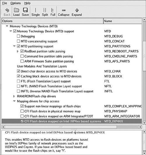 Several methods exist for communicating the partition data to the Linux kernel. The following methods are currently supported. You can see the configuration options for each in Figure 10-2 under MTD Partitioning Support.
MTD also allows configurations without partition data. In this case, MTD simply treats the entire Flash memory as a single device. 10.3.1. Redboot Partition Table PartitioningOne of the more common methods of defining and detecting MTD partitions stems from one of the original implementations: Redboot partitions. Redboot is a bootloader found on many embedded boards, especially ARM XScale boards such as the ADI Engineering Coyote Reference Platform. The MTD subsystem defines a method for storing partition information on the Flash device itself, similar in concept to a partition table on a hard disk. In the case of the Redboot partitions, the developer reserves and specifies a Flash erase block that holds the partition definitions. A mapping driver is selected that calls the partition parsing functions during boot to detect the partitions on the Flash device. Figure 10-2 shows the mapping driver for our example board; it is the final highlighted entry defining CONFIG_MTD_IXP4xx. As usual, taking a detailed look at an example helps to illustrate these concepts. We start by looking at the information provided by the Redboot bootloader for the Coyote platform. Listing 10-4 captures some of the output of the Redboot bootloader upon power-up. Listing 10-4. Redboot Messages on Power-Up
This tells us that RAM on this board is physically mapped starting at address 0x00000000 and that Flash is mapped at physical address 0x50000000 through 0x51000000. We can also see that the Flash has 128 blocks of 0x00020000 (128KB) each. Redboot contains a command to create and display partition information on the Flash. Listing 10-5 contains the output of the fis list command, part of the Flash Image System family of commands available in the Redboot bootloader. Listing 10-5. Redboot Flash Partition List
From Listing 10-5, we see that the Coyote board has three partitions defined on the Flash. The partition named RedBoot contains the executable Redboot bootloader image. The partition named RedBoot config contains the configuration parameters maintained by the bootloader. The final partition named FIS directory holds information about the partition table itself. When properly configured, the Linux kernel can detect and parse this partition table and create MTD partitions representing the physical partitions on Flash. Listing 10-6 reproduces a portion of the boot messages that are output from the aforementioned ADI Engineering Coyote board, booting a Linux kernel configured with support for detecting Redboot partitions. Listing 10-6. Detecting Redboot Partitions on Linux Boot
The first message in Listing 10-6 is printed when the Flash chip is detected, via the Common Flash Interface (CFI) driver, enabled via CONFIG_MTD_CFI. CFI is an industry-standard method for determining the Flash chip's characteristics, such as manufacturer, device type, total size, and erase block size. See Section 10.5.1, "Suggestions for Additional Reading," at the end of this chapter for a pointer to the CFI specification. CFI is enabled via the kernel-configuration utility under the Memory Technology Devices (MTD) top-level menu. Select Detect flash chips by Common Flash Interface (CFI) probe under RAM/ROM/Flash chip drivers, as illustrated in Figure 10-3. Figure 10-3. Kernel configuration for MTD CFI support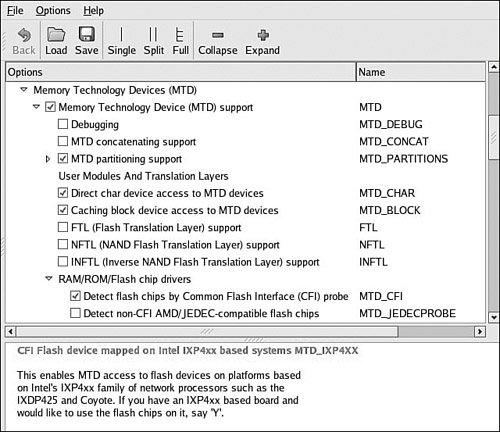 As shown in Listing 10-6, the Flash chip is detected via the CFI interface. Because we also enabled CONFIG_MTD_REDBOOT_PARTS (see Figure 10-2), MTD scans for the Redboot partition table on the Flash chip. Notice also that the chip has been enumerated with the device name IXP4XX-Flash0. You can see from Listing 10-6 that the Linux kernel has detected three partitions on the Flash chip, as enumerated previously using the fis list command in Redboot. When the infrastructure is in place as described here, the Linux kernel automatically detects and creates kernel data structures representing the three Flash partitions. Evidence of these can be found in the /proc file system when the kernel has completed initialization, as shown in Listing 10-7. Listing 10-7. Kernel MTD Flash Partitions
We can easily create a new Redboot partition. We use the Redboot FIS commands for this example, but we do not detail the Redboot commands in this book. However, the interested reader can consult the Redboot user documentation listed in Section 10.5.1 at the end of this chapter. Listing 10-8 shows the details of creating a new Redboot partition. Listing 10-8. Creating a New Redboot Partition
First, we load the image we will use to create the new partition. We will use our kernel image for the example. We load it to memory address 0x01008000. Then we create the new partition using the Redboot fis create command. We have instructed Redboot to create the new partition in an area of Flash starting at 0x50100000. You can see the action as Redboot first erases this area of Flash and then programs the kernel image. In the final sequence, Redboot unlocks its directory area and updates the FIS Directory with the new partition information. Listing 10-9 shows the output of fis list with the new partition. Compare this with the output in Listing 10-5. Listing 10-9. New Redboot Partition List
Of course, when we boot the Linux kernel, it discovers the new partition and we can operate on it as we see fit. The astute reader might have realized the other benefit of this new partition: We can now boot the kernel from Flash instead of having to load it via tftp every time. The command is illustrated next. Simply pass the Redboot exec command the Flash starting address of the partition and the length of the image to transfer into RAM. RedBoot> exec -b 0x50100000 -l 0x145cd0 Uncompressing Linux........... done, booting the kernel. ...10.3.2. Kernel Command Line PartitioningAs detailed in Section 10.3, "MTD Partitions," the raw Flash partition information can be communicated to the kernel using other methods. Indeed, possibly the most straightforward, though perhaps not the simplest method is to manually pass the partition information directly on the kernel command line. Of course, as we have already learned, some bootloaders make that easy (for example U-Boot), whereas others do not have a facility to pass a kernel command line to the kernel upon boot. In these cases, the kernel command line must be configured at compile time and, therefore, is more difficult to change, requiring a recompile of the kernel itself each time the partitions are modified. To enable command-line partitioning in the MTD subsystem, your kernel must be configured for this support. You can see this configuration option in Figure 10-2 under MTD partitioning support. Select the option for command-line partition table parsing, which defines the CONFIG_MTD_CMDLINE_PARTS option. Listing 10-10 shows the format for defining a partition on the kernel command line (taken from .../drivers/mtd/cmdlinepart.c). Listing 10-10. Kernel Command-Line MTD Partition Format
Each mtddef parameter passed on the kernel command line defines a separate partition. As shown is Listing 10-10, each mtddef definition contains multiple parts. You can specify a unique ID, partition size, and offset from the start of the Flash. You can also pass the partition a name and, optionally, the read-only attribute. Referring back to our Redboot partition definitions in Listing 10-5, we could statically define these on the kernel command line as follows: mtdparts=MainFlash:384K(Redboot),4K(config),128K(FIS),-(unused) With this definition, the kernel would instantiate four MTD partitions, with an MTD ID of MainFlash, containing the sizes and layout matching that found in Listing 10-5. 10.3.3. Mapping DriverThe final method for defining your board-specific Flash layout is to use a dedicated board-specific mapping driver. The Linux kernel source tree contains many examples of mapping drivers, located in .../drivers/mtd/maps. Any one of these will provide good examples for how to create your own. The implementation details vary by architecture. The mapping driver is a proper kernel module, complete with module_init() and module_exit() calls, as described in Chapter 8, "Device Driver Basics." A typical mapping driver is small and easy to navigate, often containing fewer than a couple dozen lines of C. Listing 10-11 reproduces a section of .../drivers/mtd/maps/pq2fads. This mapping driver defines the Flash device on a Freescale PQ2FADS evaluation board that supports the MPC8272 and other processors. Listing 10-11. PQ2FADs Flash Mapping Driver
This simple but complete Linux device driver communicates the PQ2FADS Flash mapping to the MTD subsystem. Recall from Chapter 8 that when a function in a device driver is declared with the module_init() macro, it is automatically invoked during Linux kernel boot at the appropriate time. In this PQ2FADS mapping driver, the module initialization function init_pq2fads_mtd() performs just two simple calls:
Following this simple example, you can derive a mapping driver for your own board. 10.3.4. Flash Chip DriversMTD has support for a wide variety of Flash chips and devices. Chances are very good that your chosen chip has also been supported. The most common Flash chips support the Common Flash Interface (CFI) mentioned earlier. Older Flash chips might have JEDEC support, which is an older Flash compatibility standard. Figure 10-4 shows the kernel configuration from a recent Linux kernel snapshot. This version supports many Flash types. Figure 10-4. Flash device support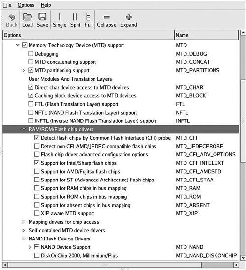 If your Flash chip is not supported, you must provide a device file yourself. Using one of the many examples in .../drivers/mtd/chips as a starting point, customize or create your own Flash device driver. Better yet, unless the chip was just introduced with some newfangled interface, chances are good that someone has already produced a driver. 10.3.5. Board-Specific InitializationAlong with a mapping driver, your board-specific (platform) setup must provide the underlying definitions for proper MTD Flash system operation. Listing 10-12 reproduces the relevant portions of .../arch/arm/mach-ixp4xx/coyote-setup.c. Listing 10-12. Coyote-Specific Board Setup
In Listing 10-12, only the relevant portions of the coyote-setup.c platform initialization file are reproduced. Starting from the bottom, the coyote_init() function calls platform_add_devices(), specifying the Coyote-specific devices defined earlier in this file. You'll notice that two devices are defined just above the coyote_init() routine. The one we're interested in for this discussion is coyote_flash. This structure of type struct platform_device contains all the important details needed by the Linux kernel and MTD subsystem. The .name member of the coyote_flash structure binds our platform-specific Flash resource to a mapping driver with the same name. You can see this in the mapping driver file .../drivers/mtd/maps/ixp4xx.c. The .resource member communicates the base address of the Flash on the board. The .dev member, which contains a .platform_data member, ties our Flash setup to a chip driver. In this case, we have specified that our board will use the CFI probe method, specified in the kernel configuration as CONFIG_MTD_CFI. You can see this configuration selection in Figure 10-4. Depending on your own architecture and board, you can use a method similar to this to define the Flash support for your own board. |
EAN: 2147483647
Pages: 167