3.3 Implementing a Microsoft Cluster
|
| < Day Day Up > |
|
3.3 Implementing a Microsoft Cluster
In this section, we walk you through the installation process for a Microsoft Cluster (also referred to as Microsoft Cluster Service or MSCS throughout the book). We also discuss the hardware and software aspects of MSCS, as well as the installation procedure.
The MSCS environment that we create in this chapter is a two-node hot standby cluster. The system will share two external SCSI drives connected to each of the nodes via a Y-cable. Figure 3-43 illustrates the system configuration.
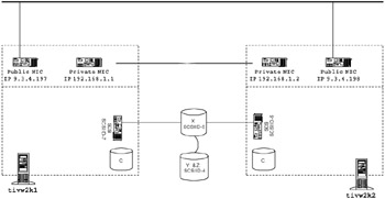
Figure 3-43: Microsoft Cluster environment
The cluster is connected using four Network Interface Cards (NICs). Each node has a private NIC and a public NIC. In an MSCS, the heartbeat connection is referred to as a private connection. The private connection is used for internal cluster communications and is connected between the two nodes using a crossover cable.
The public NIC is the adapter that is used by the applications that are running locally on the server, as well as cluster applications that may move between the nodes in the cluster. The operating system running on our nodes is Windows 2000 Advanced Edition with Service Pack 4 installed.
In our initial cluster installation, we will set up the default cluster group. Cluster groups in an MSCS environment are logical groups of resources that can be moved from one node to another. The default cluster group that we will set up will contain the shared drive X: an IP address (192.168.1.197) and a network name (tivw2kv1).
3.3.1 Microsoft Cluster hardware considerations
When designing a Microsoft Cluster, it is important to make sure all the hardware you would like to use is compatible with the Microsoft Cluster software. To make this easy Microsoft maintains a Hardware Compatibility List (HCL) found at:
-
http://www.microsoft.com/whdc/hcl/search.mspx
Check the HCL before you order your hardware to ensure your cluster configuration will be supported.
3.3.2 Planning and designing a Microsoft Cluster installation
You need to execute some setup tasks before you start installing Microsoft Cluster Service. Following are the requirements for a Microsoft Cluster:
-
Configure the Network Interface Cards (NICs)
Each node in the cluster will need two NICs: one for public communications, and one for private cluster communications. The NICs will have to be configured with static IP addresses. Table 3-14 shows our configuration.
Table 3-14: NIC IP addresses Node
IP
tivw2k1 (public)
9.3.4.197
tivw2k1 (private)
192.168.1.1
tivw2k2 (public)
9.3.4.198
tivw2k2 (private)
192.168.1.2
-
Set up the Domain Name System (DNS)
Make sure all IP addresses for your NICs, and IP addresses that will be used by the cluster groups, are added to the Domain Name System (DNS). The private NIC IP addresses do not have to be added to DNS.
Our configuration will require that the IP addresses and names listed in Table 3-15 on page 140 be added to the DNS.
Table 3-15: DNS entries required for the cluster Hostname
IP Address
tivw2k1
9.3.4.197
tivw2k2
9.3.4.198
tivw2kv1
9.3.4.199
tivw2kv2
9.3.4.175
-
Set up the shared storage
When setting up the shared storage devices, ensure that all drives are partitioned correctly and that they are all formatted with the NT filesystem (NTFS). When setting up the drives, ensure that both nodes are assigned the same driver letters for each partition and are set up as basic drives.
We chose to set up our drive letters starting from the end of the alphabet so we would not interfere with any domain login scripts or temporary storage devices.
If you are using SCSI drives, ensure that the drives are all using different SCSI IDs and that the drives are terminated correctly.
When you partition your drives, ensure you set up a partition specifically for the quorum. The quorum is a partition used by the cluster service to store cluster configuration database checkpoints and log files. The quorum partition needs to be at least 100 MB in size.
Important: Microsoft recommends that the quorum partition be on a separate disk and also recommends the partition be 500 MB in size
Table 3-16 illustrates how we set up our drives.
Table 3-16: Shared drive partition table Disk
Drive Letter
Size
Label
Disk 1
X:
34 GB
Partition1
DIsk 2
Y:
33.9 GB
Partition 2
Z:
100 MB
Quorum
Note When configuring the disks, make sure that you configure them on one node at a time and that the node that is not being configured is powered off. If both nodes try to control the disk at the same time, they may cause disk corruption.
-
Update the operating system
Before installing the cluster service, connect to the Microsoft Software Update Web site to ensure you have all the latest hardware drivers and software patches installed. The Microsoft Software Update Web site can be found at:
http://windowsupdate.microsoft.com
-
Create a domain account for the cluster
The cluster service requires that a domain account be created under which the cluster service will run. The domain account must be a member of the administrator group on each of the nodes in the cluster. Make sure you set the account so that the user cannot change the password and that the password never expires. We created the account "cluster_service" for our cluster.
-
Add nodes to the domain
The cluster service runs under a domain account. In order for the domain account to be able to authenticate against the domain controller, the nodes must join the domain where the cluster user has been created.
3.3.3 Microsoft Cluster Service installation
Here we discuss the Microsoft Cluster Service installation process. The installation is broken into three sections: installation of the primary node; installation of the secondary node; and configuration of the cluster resources.
Following is a high-level overview of the installation procedure. Detailed information for each step in the process are provided in the following sections.
Installation of the MSCS node 1
| Important: | Before starting the installation on Node 1, make sure that Node 2 is powered off. |
The cluster service is installed as a Windows component. To install the service, the Windows 2000 Advanced Server CD-ROM should be in CD-ROM drive. You can save time by copying the i386 directory from the CD to the local drive.
-
To start the installation, open the Start menu and select Settings -> Control Panel and then double-click Add/Remove Programs.
-
Click Add/Remove Windows Components, located on the left side of the window. Select Cluster Service from the list of components as shown in Figure 3-44, then click Next.
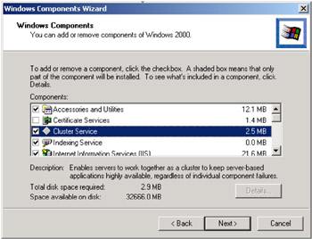
Figure 3-44: Windows Components Wizard -
Make sure that Remote administration mode is checked and click Next (Figure 3-45). You will be asked to insert the Windows 2000 Advanced Server CD if it is not already inserted. If you copied the CD to the local drive, select the location where it was copied.
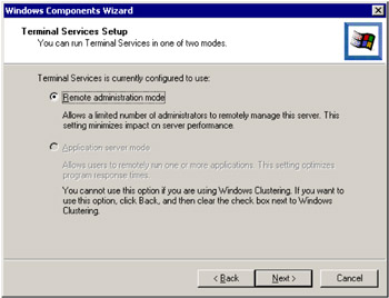
Figure 3-45: Windows Components Wizard -
Click Next at the welcome screen (Figure 3-46).
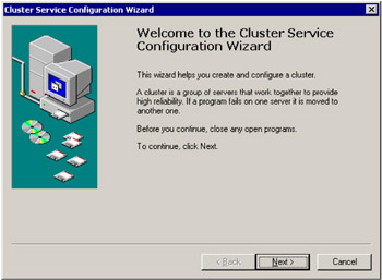
Figure 3-46: Welcome screen -
The next window (Figure 3-47) is used by Microsoft to verify that you are aware that it will not support hardware that is not included in its Hardware Compatibility List (HCL).
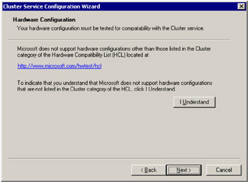
Figure 3-47: Hardware ConfigurationTo move on to the next step of the installation, click I Understand and then click Next.
-
Now that we have located the installation media and have acknowledged the support agreement we can start the actually installation. The next screen is used to select whether you will be installing the first node or any additional node.
We will install the first node in the cluster at this point so make sure that the appropriate radio button is selected and click Next (Figure 3-48). We will return to this screen again later when we install the second node in the cluster.
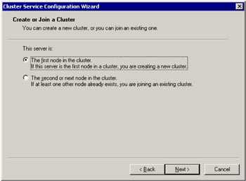
Figure 3-48: Create or Join a Cluster -
We must now name our cluster. The name is the local name associated with the whole cluster. This is not the virtual name that is associated with the a cluster group. This is used by the Microsoft Cluster Administrator utility to administer the cluster resources.
We prefer to use the same as the hostname to prevent confusion. In this case we call it TIVW2KV1. After you have entered a name for your cluster, click Next (Figure 3-49).
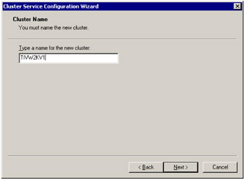
Figure 3-49: Cluster Name -
The next step is to enter the domain account that the cluster service will use. See the pre-installation setup section for details on setting up the domain account that the cluster service will use. Click Next (Figure 3-50).
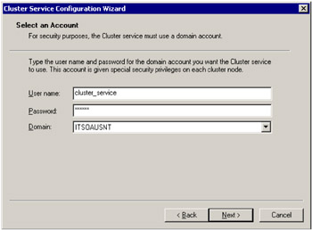
Figure 3-50: Select an Account -
The next window is used to determine the disks that the cluster service will manage. In the example we have two partitions, one for the quorum and another for the data. Make sure both are set up as managed disks. Click Next (Figure 3-51).
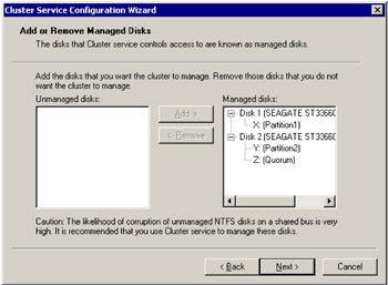
Figure 3-51: Add or Remove Managed Disks -
We now need to select where the cluster checkpoint and log files will be stored. This disk is referred to as the Quorum Disk. The quorum is a vital part of the cluster as it used for storing critical cluster files. If the data on the Quorum Disk becomes corrupt, the cluster will be unusable.
It is important to back up this data regularly so you will be able to recover your cluster. It is recommended that you have at least 100 MB on a separate partition for reserved for this purpose; refer to the preinstallation setup section on disk preparation.
After you select your Quorum Disk, select Next. (Figure 3-52).
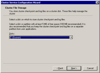
Figure 3-52: Cluster File Storage -
The next step is to configure networking. A window will pop up to recommend that you use multiple public adapters to remove any single point of failure. Click Next to continue (Figure 3-53).
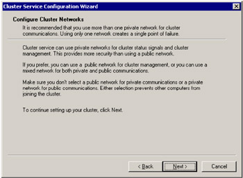
Figure 3-53: Warning window -
The next section will prompt you to identify each NIC as either public, private or both. Since we named our adapters ahead of time, this is easy. Set the adapter that is labeled Public Network Connection as Client access only (public network). Click Next (Figure 3-54).
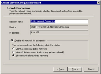
Figure 3-54: Network Connections - All communications -
Now we will configure the private network adapter. This adapter is used as a heartbeat connection between the two nodes of the cluster and is connected via a crossover cable.
Since this adapter is not accessible from the public network, this is considered a private connection and should be configured as Internal cluster communications only (private network). Click Next (Figure 3-55).
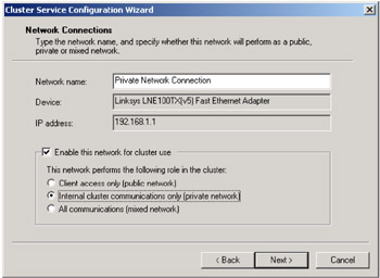
Figure 3-55: Network Connections - Internal cluster communications only (private network) -
Because we configured two adapters to be capable of communicating as private adapters, we need to select the priority in which the adapters will communicate.
In our case, we want the Private Network Connection to serve as our primary private adapter. We will use the Public Network Connection as our backup adapter. Click Next to continue (Figure 3-56).
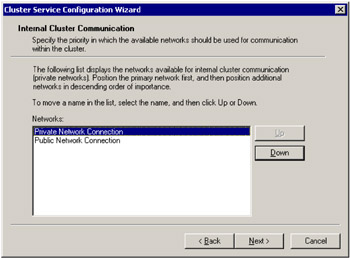
Figure 3-56: Network priority setup -
Once the network adapters have been configured, it is time to create the cluster resources. The first cluster resource is the cluster IP address. The cluster IP address is the IP address associated with the cluster resource group; it will follow the resource group when it is moved from node to node. This cluster IP address is commonly referred to as the virtual IP.
Set up the cluster IP address you will need to enter the IP address and subnet mask that you plan to use, and select the Public Network Connection as the network to use. Click Next (Figure 3-57).
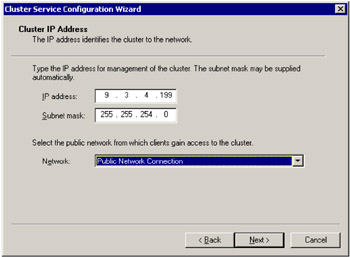
Figure 3-57: Cluster IP Address -
Click Finish to complete the cluster service configuration (Figure 3-58).
Figure 3-58: Cluster Service Configuration Wizard -
The next window is just an informational pop-up letting you know that the Cluster Administrator application is now available. The cluster service is managed using the Cluster Administrator tool. Click OK (Figure 3-60 on page 157).

Figure 3-59: Cluster Service Configuration Wizard -
Click Finish one more time to close the installation wizard (Figure 3-60).
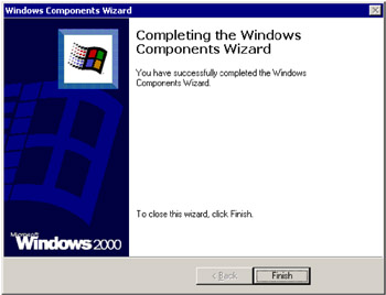
Figure 3-60: Windows Components Wizard
At this point, the installation of the cluster service on the primary node is compete. Now that we have created a cluster, we will need to add additional nodes to the cluster.
Installing the second node
The next step is to install the second node in the cluster. To add the second node, you will have to perform the following steps on the secondary node. The installation of the secondary node is relatively easy, since the cluster is configured during the installation on the primary node. The first few steps are identical to installing the cluster service on the primary node.
To install the cluster service on the secondary node:
-
Go to the Start Menu and select Settings -> Control Panel and double-click Add/Remove Programs.
-
Click Add/Remove Windows Components, located on the left side of the window, and then select Cluster Service from the list of components. Click Next to start the installation (Figure 3-61).
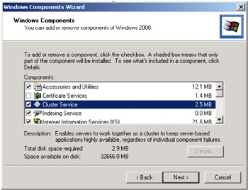
Figure 3-61: Windows Components Wizard -
Make sure the Remote administration mode is selected (Figure 3-62); it should be the only option available. Click Next to continue.
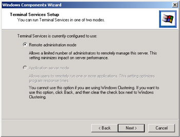
Figure 3-62: Windows Components Wizard -
Click Next past the welcome screen (Figure 3-63).
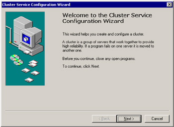
Figure 3-63: Windows Components Wizard -
Once again you will have to verify that the hardware that you have selected is compatible with the software you are installing and that you understand that Microsoft will not support software not on the HCL. Click I Understand and then Next to continue (Figure 3-64).
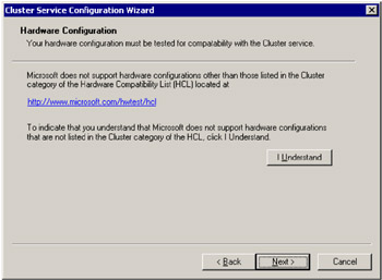
Figure 3-64: Hardware Configuration -
The next step is to select that you will be adding the second node to the cluster. Once the second node option is selected, click Next to continue (Figure 3-65).
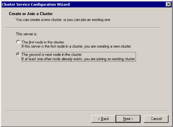
Figure 3-65: Create or Join a Cluster -
You will now have to type in the name of the cluster that you would like the second node to be a member. Since we set up a domain account to be used for the cluster service, we will not need to check the connect to cluster box. Click Next (Figure 3-66).
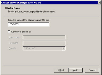
Figure 3-66: Cluster Name -
The next window prompts you for a password for the domain account that we installed the primary node with. Enter the password and click Next (Figure 3-67).
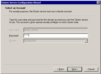
Figure 3-67: Select an Account -
Click Finish to complete the installation (Figure 3-68).
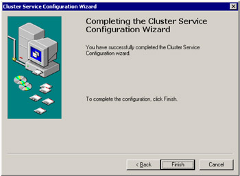
Figure 3-68: Finish the installation -
The next step is to verify that the cluster works. To verify that the cluster is operational, we will need to open the Cluster Administrator. You can open the Cluster Administrator in the Start Menu by selecting Programs -> Administrative Tools -> Cluster Administrator (Figure 3-69).
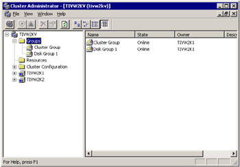
Figure 3-69: Verifying that the cluster worksYou will notice that the cluster will have two groups: one called cluster group, and the other called Disk Group 1:
-
The cluster group is the group that contains the virtual IP and name and cluster shared disk.
-
Disk Group 1 at this time only contains our quorum disk.
In order to verify that the cluster is functioning properly, we need to move the cluster group from one node to the other. You can move the cluster group by right-clicking the icon and selecting Move Group.
After you have done this, you should see the group icon change for a few seconds while the resources are moved to the secondary node. Once the group has been moved, you should see that the icon return to normal and the owner of the group should now be the second node in the cluster.
-
The cluster service is now installed and we are ready to start adding applications to our cluster groups.
Configuring the cluster resources
Now it is time to configure the cluster resources. The default setup using the cluster service installation wizard is not optimal for our Tivoli environment. For the scenarios used later in this book, we have to set up the cluster resources for a mutual takeover scenario. To support this, we have to modify the current resource groups and add two resources. Figure 3-70 illustrates the desired configuration.
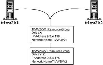
Figure 3-70: Cluster resource diagram
The following steps will guide you through the cluster configuration.
-
The first step is to rename the cluster resource groups.
-
Right-click the cluster group containing the Y: and Z: drive resource and select Rename (Figure 3-71). Enter the name TIVW2KV1.
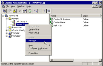
Figure 3-71: Rename the cluster resource groups -
Right-click the cluster group containing the X: drive resource and select Rename. Enter the name TIVW2KV2.
-
-
Now we will need to move the disk resources to the correct groups.
-
Right-click the Disk Y: Z: resource under the TIVW2KV1 resource group and select Change Group -> TIVW2KV2 as shown in Figure 3-72.
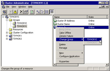
Figure 3-72: Changing resource groups -
Press Yes to complete the move (Figure 3-73).
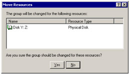
Figure 3-73: Resource move confirmation -
Right -lick the Disk X: resource under the TIVW2KV2 resource group and select Change Group -> TIVW2KV1.
-
Press Yes to complete the move.
-
-
The next step is to rename the resources. We do this so we can determine which resource group a resource belongs to by it name.
-
Right-click the Cluster IP Address resource under the TIVW2KV1 resource group and select Rename (Figure 3-74). Enter the name TIVW2KV1 - Cluster IP Address.
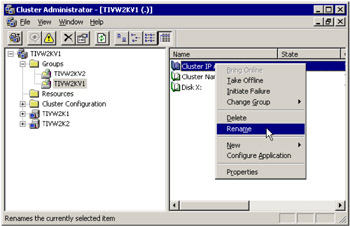
Figure 3-74: Rename resources -
Right-click the Cluster Name resource under the TIVW2KV1 resource group and select Rename. Enter the name TIVW2KV1 - Cluster Name.
-
Right- click the Disk X: resource under the TIVW2KV1 resource group and select Rename. Enter the name TIVW2KV1 - Disk X:.
-
Right-click the Disk Y: Z: resource under the TIVW2KV2 resource group and select Rename. Enter the name TIVW2KV2 - Disk Y: Z:.
-
-
We now need to add two resources under the TIVW2KV2 resource group. The first resource we will add is the IP Address resource.
-
Right-click the TIVW2KV2 resource group and select New -> Resource (Figure 3-75).
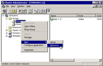
Figure 3-75: Add a new resource -
Enter TIVW2KV2 - IP Address in the name field and set the resource type to IP address. Click Next (Figure 3-76).
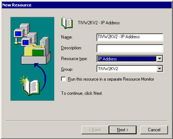
Figure 3-76: Name resource and select resource type -
Select both TIVW2K1 and TIVW2K2 and possible owners of the resource. Click Next (Figure 3-77).
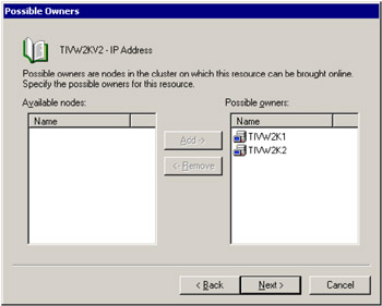
Figure 3-77: Select resource owners -
Click Next past the dependencies screen; no dependencies need to be defined at this time (Figure 3-78).
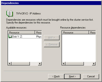
Figure 3-78: Dependency configuration -
The next step is to configure the IP address associated with the resource. Enter the IP address 9.3.4.175 in the Address field and add the subnet mask of 255.255.255.254. Make sure the Public Network Connection is selected in the Network field and the Enable NetBIOS for this address box is checked. Click Next (Figure 3-79).
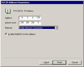
Figure 3-79: Configure IP address -
Click OK to complete the installation (Figure 3-80).

Figure 3-80: Completion dialog
-
-
Now that the IP address resource has been created, we need to create the Name resource for the TIVW2KV2 cluster group.
-
Right-click the TIVW2KV2 resource group and select New -> Resource (Figure 3-81).
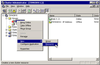
Figure 3-81: Adding a new resource -
Set the name of the resource to TIVW2KV2 - Cluster Name and specify the resource type to be Network Name. Click Next (Figure 3-82).
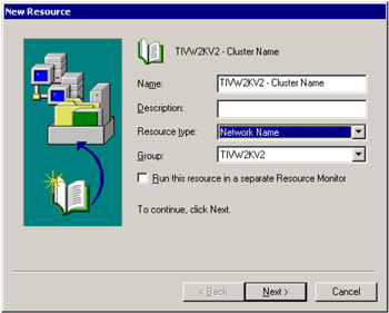
Figure 3-82: Specify resource name and type -
Next select both TIVW2K1 and TIVW2K2 as possible owners of the resource. Click Next (Figure 3-83).

Figure 3-83: Select resource owners -
Click Next in the Dependencies screen (Figure 3-84). We do not need to configure these at this time.
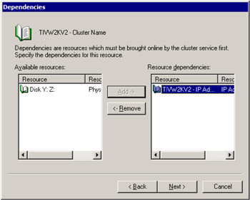
Figure 3-84: Resource dependency configuration -
Next we will enter the cluster name for the TIVW2KV2 resource group. Enter the cluster name TIVW2KV2 in the Name field. Click Next (Figure 3-85).
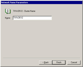
Figure 3-85: Cluster name -
Click OK to complete the cluster name configuration (Figure 3-86).

Figure 3-86: Completion dialog
-
-
The final step of the cluster configuration is to bring the TIVW2KV2 resource group online. To do this, right-click the TIVW2KV2 resource group and select Bring Online (Figure 3-87).
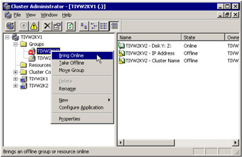
Figure 3-87: Bring resource group online
This concludes our cluster configuration.
|
| < Day Day Up > |
|
EAN: 2147483647
Pages: 92