WAN Design
|
When either redesigning an existing network or building a new network from scratch, you have to include WAN technologies in your design, that is, unless you only have one building to configure, of course. Understanding the different WAN technologies and protocols is critical in your design process.
Since 1997, when the 802.11 wireless specifications were released, WAN technologies have changed dramatically. Before wireless networking, your only option was to either put in copper or fiber cable between buildings or lease copper or fiber connections from a provider. Although wireless is an important part of WAN and LAN design, the current CCDA objectives do not cover wireless technologies, so this section discusses the current options that you can lease from a provider. Let’s move on to discuss the feasible WAN protocols that you can use in your design.
WAN Protocols
It is important to understand as many protocols supported by Cisco as possible. As you understand the different WAN protocols, you make better design decisions. This section discusses the following Cisco-supported WAN protocols:
-
SDLC
-
HDLC
-
ISDN
-
PPP
-
Frame Relay
-
DSL
SDLC
SDLC (Synchronous Data Link Control) was developed by IBM during the mid-1970s for use in SNA (Systems Network Architecture) environments. Subsequent to the implementation of SDLC by IBM, SDLC formed the foundation for numerous similar protocols, including HDLC and LAPB.
Bit-synchronous protocols owe their success to their expanded efficiency, flexibility, and in some cases, greater speed, with SDLC in the lead as the chief SNA Data Link layer protocol for WAN links. Versatile SDLC supports many link types and topologies, such as
-
Point-to-point and multi-point links
-
Bounded and unbounded media
-
Half-duplex and full-duplex transmission facilities
-
Circuit and packet-switched networks
SDLC also supports two network node types:
Primary stations Primary stations control the operation of other stations; poll secondaries in a predetermined order; and set up, tear down, and manage links.
Secondary stations Secondary stations are controlled by a primary station. If a secondary station is polled, it can transmit outgoing data. An SDLC secondary station can send information only to the primary station, and even then only after the primary station grants permission.
HDLC
The HDLC (High-Level Data Link Control) protocol is a popular ISO- standard, bit-oriented, Data Link layer protocol that specifies an encapsulation method for data on synchronous serial data links.
HDLC’s development began when the ISO modified SDLC and came up with HDLC. Thereafter, the ITU-T (International Telecommunication Union Telecommunication Standardization Sector) tweaked HDLC a bit more and released Link Access Procedure (LAP), and then LAPB (Link Access Procedure, Balanced). After that, the IEEE (Institute of Electrical and Electronic Engineers) went to work on HDLC, and the result was the IEEE 802.2 specification.
HDLC is the default encapsulation used by Cisco routers over synchronous serial links. Cisco’s HDLC is proprietary—it won’t communicate with any other vendor’s HDLC implementation. But don’t give Cisco grief for it— everyone’s HDLC implementation is proprietary. When we discussed our routers in Chapter 5, “Designing Modular Network Topologies,” we were using HDLC encapsulation on all of our serial links.
Transfer Modes
HDLC supports the following transfer modes:
Normal response mode (NRM) NRM is implemented with SDLC. Under NRM, a secondary can’t communicate with a primary until the primary asks it to.
Asynchronous response mode (ARM) ARM allows secondaries to communicate with a primary without permission from it.
Asynchronous balanced mode (ABM) ABM introduced the combined node—one that can act as either a primary station or as a secondary station. All ABM communication takes place between a number of combined nodes, and combined stations can originate transmissions without permission.
LAPB Integrated into the X.25 protocol stack, LAPB shares the same frame format, frame types, and field functions as both SDLC and HDLC. It’s confined to the ABM transfer mode, and with it, you can establish circuits with either DTE (data terminal equipment) or DCE (data communications equipment). Devices that initiate communication are deemed primaries, and those that respond are deemed secondaries.
ISDN
ISDN (Integrated Services Digital Network) is a digital service designed to run over existing telephone networks—the ability to deliver a true digital service across your existing local loop is very cool indeed. ISDN can support both data and voice—a telecommuter’s dream. ISDN applications require bandwidth, because typical ISDN applications and implementations include high-speed image applications (such as Group IV facsimile), high-speed file transfer, video conferencing, and multiple links into homes of telecommuters.
ISDN is actually a set of communication protocols proposed by telephone companies that allows them to carry data and voice. It gives you a group of digital services that simultaneously convey data, text, voice, music, graphics, and video to end users, and it was designed to achieve this over the telephone systems already in place. ISDN is referenced by a suite of ITU-T standards encompassing the OSI model’s Physical, Data Link, and Network layers.
ISDN Terminals
Devices connecting to the ISDN network are known as terminals, and there are two types:
TE1 Terminal equipment type 1 refers to those terminals that understand ISDN standards.
TE2 Terminal equipment type 2 refers to those terminals that predate ISDN standards. To use a TE2, you have to use a terminal adapter (TA).
ISDN Reference Points
ISDN has four reference points that define logical interfaces:
R reference point The R reference point defines the reference point between non-ISDN equipment (TE2) and a TA.
S reference point The S reference point defines the reference point between user terminals and an NT2.
T reference point The T reference point defines the reference point between NT1 and NT2 devices.
U reference point The U reference point defines the reference point between NT1 devices and line-termination equipment in a carrier network. (This is only in North America where the NT1 function isn’t provided by the carrier network.)
ISDN Protocols
ISDN protocols are defined by the ITU, and there are several series of protocols dealing with diverse issues:
-
Protocols beginning with the letter E deal with using ISDN on the existing telephone network.
-
Protocols beginning with the letter I deal with concepts, terminology, and services.
-
Protocols beginning with the letter Q cover switching and signaling.
ISDN Switch Types
AT&T and Nortel are responsible for the majority of the ISDN switches in place today, but additional companies also make them. In Table 6.1, under “Keyword,” you’ll find the right keyword to use along with the isdn switch- type command to configure a router for the variety of switches to which it’s going to connect. If you don’t know which switch your provider is using at their central office, simply call them to find out.
| Switch Type | Keyword |
|---|---|
| AT&T basic rate switch | Basic-5ess |
| Nortel DMS-100 basic rate switch | Basic-dms100 |
| National ISDN-1 switch | Basic-ni1 |
| AT&T 4ESS (ISDN PRI only) | Primary-4ess |
| AT&T 5ESS (ISDN PRI only) | Primary-5ess |
| Nortel DMS-100 (ISDN PRI only) | Primary-dms100 |
Basic Rate Interface
ISDN BRI (Basic Rate Interface) service provides two B channels and one D channel. The BRI B channel service operates at 64Kbps and carries data. The BRI D channel service operates at 16Kbps and usually carries control and signaling information. The D channel signaling protocol spans the OSI reference model’s Physical, Data Link, and Network layers. BRI also provides framing control for a total bit rate of up to 144Kbps.
When configuring ISDN BRI, you’ll need to obtain SPIDs (service profile identifiers), and you should have one SPID for each B channel—two for BRI. You can think of SPIDs as the telephone number of each B channel. The ISDN device gives the SPID to the ISDN switch, which then allows the device to access the network for BRI or PRI service. Without a SPID, many ISDN switches don’t allow an ISDN device to place a call on the network. Not all configurations require unique SPIDs, however. Some are autosensed. Ask your service provider to be sure.
ISDN BRI was developed and released by many telephone companies in the early 1980s as a solution to digital signaling over an existing pair of copper wires supporting simultaneous voice, video, and data. In North America, the NT1 is provided by the subscriber and is usually built into a TE1 device such as a router or modem card and connects to the U reference point or loop, back to the central office.
ISDN BRI is often used in SOHO (small office, home office) networks as a primary connection for voice, video, and data traffic. It is also used as a backup connection for larger networks that use Frame Relay as their primary connection. ISDN in a SOHO network affords users with proper equipment the benefit of sharing a single line for voice and data. Cisco routers are available with local POTS (plain old telephone service) connections for voice traffic using standard telephones. ISDN-capable telephones are an option when connecting directly to ISDN but are generally more expensive. In most cases, one of the ISDN data channels must disconnect to allow a voice call, but that leaves the other channel available and connected for data. Proper planning and configuration is crucial when defining the use of the POTS connections at the router since users need to decide if voice calls will override data and issue the proper Cisco IOS commands into running config.
ISDN BRI as a backup to Frame Relay requires more hardware and configuration. In some cases, a Cisco router can be equipped with interfaces for Frame Relay and ISDN, or two routers can be used and configured for backup using floating static routes and DDR. For more information, see the article “Configuring ISDN Backup for WAN Links Using Floating Static Routes” at the URL http://www.cisco.com/warp/public/125/fr_isdn_backup.html.
Primary Rate Interface
The ISDN Primary Rate Interface (PRI) service delivers 23 B channels and one 64Kbps D channel in North America and Japan, for a total bit rate of up to 1.544Mbps.
In Europe, Australia, and other parts of the world, ISDN provides 30 B channels and one 64Kbps D channel, for a total bit rate of up to 2.048Mbps.
Dial-on-Demand Routing (DDR)
DDR is a common use of ISDN. With it, the administrator can define “interesting” traffic on the router and initiate WAN links based on that traffic. Access lists define interesting traffic, so there’s a great deal of flexibility given to the administrator. For instance, an expensive ISDN connection to the Internet can be initiated to retrieve e-mail, but not for a WWW request. DDR is an effective tool in situations where WAN access is charged in some time interval, and it’s best to use it in situations where WAN access is infrequent.
DDR provides the missing software ingredient for creating a fully functional backup system. Versatile DDR can be used over several different types of connections and is supported in Cisco IOS version 9 and later. It supports the networking protocols IP, IPX, AppleTalk, and others. DDR’s flexibility reaches even further. It can be used over several different types of interfaces— synchronous and asynchronous serial interfaces, as well as ISDN.
PPP
PPP (Point-to-Point Protocol) is a data-link protocol that can be used over either asynchronous (dial-up) or synchronous (ISDN) media and that uses LCP (Link Control Protocol) to build and maintain data-link connections.
The basic purpose of PPP is to transport Layer 3 packets across point-to-point links. Figure 6.2 shows the protocol stack compared to the OSI Reference model.
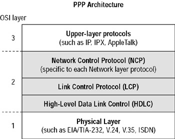
Figure 6.2: Point-to-point protocol stack
PPP contains four main components:
EIA/TIA-232-C EIA/TIA-232-C is the Physical layer international standard for serial communication.
HDLC HDLC is a method for encapsulating datagrams over serial links.
LCP LCP provides a method of establishing, configuring, maintaining, and terminating the point-to-point connection.
NCP NCP (Network Control Protocol) is used for establishing and configuring different Network layer protocols. PPP is designed to allow the simultaneous use of multiple Network layer protocols. Two examples of protocols here are IPCP (IP Control Protocol) and IPXCP (Internetwork Packet Exchange Control Protocol).
Another new PPP feature is the support for multiple protocols. SLIP supported only IP, but through NCP, PPP supports IP, IPX, AppleTalk, DECnet, OSI/CLNS, and transparent bridging. NCP is actually a family of protocols—one for each Layer 3 protocol supported by PPP. PPP specifies an authentication mechanism, while CHAP and PAP are typically used. It is extensible so other companies (like Microsoft) can implement their own security.
Multilink PPP
By using ISDN with PPP encapsulation, Cisco routers can support multiple connections over the same physical interface. This allows Cisco routers to use dial-up connections to establish more than one connection at a time to an access server. Why would you want a router to be able to do that? Because if it can, you’re granted twice the bandwidth of a single dial-up line. The capacity to increase bandwidth between point-to-point dial-up connections by grouping interfaces, then splitting and recalculating packets to run over that group of interfaces, is called multilink.
Before you can run multilink, you must define the interesting packets using the dialer-list global command. This command directs the router to search for specific network protocols for making and keeping a link active. You can apply a dialer list to an interface using the subcommand dialer-group.
Frame Relay
Recently, the high-performance WAN encapsulation method known as Frame Relay has become one of the most popular technologies in use. It operates at the Physical and Data Link layers of the OSI reference model and was originally designed for use across ISDN interfaces. But today, Frame Relay is used over a variety of other network interfaces.
Cisco Frame Relay supports the following protocols:
-
IP
-
DECnet
-
AppleTalk
-
Xerox Network Service (XNS)
-
Novell IPX
-
Connectionless Network Service (CLNS)
-
International Organization for Standards (ISO)
-
Banyan VINES
-
Transparent bridging
Frame Relay provides a communications interface between DTE and DCE devices. DTE consists of terminals, PCs, routers, and bridges— customer-owned end node and internetworking devices. DCE consists of carrier-owned internetworking devices.
Popular opinion maintains that Frame Relay is more efficient and faster than X.25 because it assumes error checking will be done through higher layer protocols and application services.
Frame Relay provides connection-oriented, Data Link layer communication via virtual circuits just as X.25 does. These virtual circuits are logical connections created between two DTEs across a packet-switched network, which is identified by a DLCI (data-link connection identifier). (We’ll get to DLCIs in a bit.) Also, like X.25, Frame Relay uses both PVCs (permanent virtual circuits) and SVCs (switched virtual circuits), although most Frame Relay networks use PVCs.
Frame Relay with Cisco Routers
When configuring Frame Relay on Cisco routers, you need to specify it as an encapsulation on serial interfaces. There are only two encapsulation types: Cisco and IETF (Internet Engineering Task Force). The following router output shows the two different encapsulation methods when choosing Frame Relay on your Cisco router:
RouterA(config)#int s0 RouterA(config-if)#encapsulation frame-relay ? ietf Use RFC1490 encapsulation <cr>
The default encapsulation is Cisco unless you manually type in IETF, and Cisco is the type used when connecting two Cisco devices. You opt for the IETF encapsulation if you need to connect a Cisco device to a non-Cisco device with Frame Relay. So before choosing an encapsulation type, check with your ISP and find out which one they use. (If they don’t know, hook up with a different ISP!)
DLCIs (Data Link Connection Identifiers)
Frame Relay PVCs are identified by DLCIs. A Frame Relay service provider such as the telephone company typically assigns DLCI values, which are used by Frame Relay to distinguish between different virtual circuits on the network. Since many virtual circuits can be terminated on one multi-point Frame Relay interface, many DLCIs are often affiliated with it.
For the IP devices at each end of a virtual circuit to communicate, their IP addresses need to be mapped to DLCIs. This mapping can function as a multi-point device—one that can identify to the Frame Relay network the appropriate destination virtual circuit for each packet that is sent over the single physical interface. The mappings can be done dynamically through IARP (Inverse ARP) or manually through the Frame Relay map command.
Frame Relay uses DLCIs the same way that X.25 uses X.121 addresses, and every DLCI number can be given either global or local meaning everywhere within the Frame Relay network. However, the customary implementation is to give each DLCI local meaning. What does this mean? It means that DLCI numbers do not necessarily need to be unique. Two DLCI numbers can be the same on different sides of a link, because Frame Relay maps a local DLCI number to a virtual circuit on each interface of the switch.
Configuring a DLCI number to be applied to an interface is as follows:
RouterA(config-if)#frame-relay interface-dlci ? <16-1007> Define a DLCI as part of the current subinterface RouterA(config-if)#frame-relay interface-dlci 16
LMI (Local Management Interface)
The LMI (Local Management Interface) was developed in 1990 by Cisco Systems, StrataCom, Northern Telecom, and Digital Equipment Corporation, and became known as the Gang-of-Four LMI or Cisco LMI. This gang took the basic Frame Relay protocol from the CCIT and added extensions onto the protocol features that allow internetworking devices to communicate easily with a Frame Relay network.
The LMI global-addressing extension gives Frame Relay DLCI values global rather than local significance. DLCI values become DTE addresses that are unique in the Frame Relay WAN. The global-addressing extension adds functionality and manageability to Frame Relay internetworks. Individual network interfaces and the end nodes attached to them, for example, can be identified by using standard address-resolution and discovery techniques. In addition, the entire Frame Relay network appears to be a typical LAN to routers on its periphery.
The LMI is a signaling standard between a CPE device and a frame switch. The LMI is responsible for managing and maintaining status between these devices. LMI messages provide information about the following:
Keepalives Keepalives verify that data is flowing.
Multicasting Multicasting provides a local DLCI PVC.
Multicast addressing Multicast addressing provides global significance.
The status of virtual circuits The status of virtual circuits provides DLCI status.
| Note | Beginning with IOS version 11.2, the LMI type is autosensed. This enables the interface to determine the LMI type supported by the switch. |
If you’re not going to use the autosense feature, you’ll need to check with your Frame Relay provider to find out which LMI type to use instead. The default type is Cisco, but you may need to change to ANSI or Q.933A. The three different LMI types are depicted in the following router output:
RouterA(config-if)#frame-relay lmi-type ? cisco ansi q933a
As seen in the output, all three standard LMI signaling formats are supported:
Cisco Cisco is the LMI type defined by the Gang of Four. This is the default LMI type.
ANSI Annex D defined by ANSI standard T1.617
ITU-T (q933a) Annex A defined by Q.933
Subinterfaces
You can have multiple virtual circuits on a single serial interface and yet treat each as a separate interface. These are known as subinterfaces. Think of a subinterface as a hardware interface defined by the IOS software.
One advantage gained through using subinterfaces is the ability to assign different Network layer characteristics to each subinterface and virtual circuit, such as IP routing on one virtual circuit and IPX on another.
Partial Mesh Networks
You can use subinterfaces to mitigate partial mesh Frame Relay networks and split-horizon protocols. For example, say you are running the IP protocol on a LAN network. If they’re on the same physical network, Router A can talk to Router B, and Router B can talk to Router C—you can usually assume that Router A can talk to Router C. Though this is true with a LAN, it’s not true with a Frame Relay network, unless Router A has a virtual circuit to Router C.
In Figure 6.3, Network 1 is configured with five locations. To be able to make this network function, you would have to create a meshed network as shown in Network 2. However, even though Network 2’s example works, it’s an expensive solution—configuring subinterfaces as shown in the Network 3 solution is much more cost-effective.
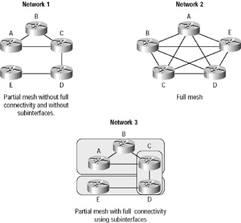
Figure 6.3: Partial meshed network examples
In Network 3, configuring subinterfaces actually works to subdivide the Frame Relay network into smaller subnetworks—each with its own network number. So locations A, B, and C connect to a fully meshed network, while locations C and D and locations D and E are connected via point-to-point connections. Locations C and D connect to two subinterfaces and forward packets.
Defining Subinterfaces
You define subinterfaces with the int s0. subinterface number command as follows:
RouterA(config)#int s0 RouterA(config)#encapsulation frame-relay RouterA(config)#int s0.? <0-4294967295> Serial interface number RouterA(config)#int s0.16 ? multipoint Treat as a multipoint link point-to-point Treat as a point-to-point link
You can define an almost limitless number of subinterfaces on a given physical interface. However, you can only define as many subinterfaces as the router will support. Each subinterface takes an IDB (interface description block); on a 2500, you only have 255 total IDBs. In the preceding example, we chose to use subinterface 16, because that represents the DLCI number assigned to that interface. However, you can choose any number between 0 and 4,292,967,295.
There are two types of subinterfaces:
Point-to-point A point-to-point subinterface is used when a single virtual circuit connects one router to another.
Multi-point A multi-point subinterface is used when the router is the center of a star of virtual circuits.
Frame Relay Congestion Control
Frame Relay includes many “control” parameters for traffic congestion control.
DE (Discard Eligible) When a Frame Relay router detects congestion on the Frame Relay network, it will turn the DE bit on in a Frame Relay packet header. The Frame Relay switch will discard the packets with the DE bit set first.
FECN (Forward Explicit Congestion Notification) When the Frame Relay network recognizes congestion in the cloud, the switch will set the FECN bit in a Frame Relay packet to tell the destination that the path just traversed is congested.
BECN (Backward Explicit Congestion Notification) When the switch detects congestion in the Frame Relay network, it will set the BECN bit in a Frame Relay packet and send it to the source router, telling it to slow down the rate at which it is transmitting packets.
CIR (Committed Information Rate)
Frame Relay providers allow customers to buy a lower amount of bandwidth than what they really might need. This is called the committed information rate (CIR). What this means is that the customer can buy bandwidth of, for example, 256k, but it is possible to burst up to T1 speeds. The CIR specifies that as long as the data input by a device to the Frame Relay network is below or equal to the CIR, then the network will continue to forward data for the PVC. However, if data rates do exceed the CIR, it is not guaranteed.
It is sometimes possible to also purchase a Bc (committed burst), that allows customers to exceed their CIR for a specified amount of time. In this situation, the DE bit will always be set.
Choose a CIR based on realistic, anticipated traffic rates. Some Frame Relay providers allow you to purchase a CIR of zero. You can use a zero CIR to save money if retransmission of packets is acceptable. DSL (Digital Subscriber Line)
DSL is a technology that allows ordinary PSTN copper to be used for high- speed data communications. In essence, it is a new way of using existing infrastructure. Given the amount of installed copper, it is no wonder that DSL has become such a popular option.
Most readers of this book will be familiar with DSL as an Internet- connectivity technology. As mentioned earlier, when using public networks to connect diverse sites, DSL—in conjunction with VPN technology—may well prove to be a cost-effective and viable solution. However, this is not the only flavor of DSL available. There are several types of DSL that may be appropriate in different situations:
ADSL (asymmetric DSL) ADSL, as the word asymmetric implies, has differing upload and download capacities. From the end-site perspective, there is a maximum upload capability of 2Mbps and a maximum download capability of 8Mbps. Varieties of ADSL vary depending on service providers, and symmetric configurations up to 640kbps are possible. ADSL also allows a PSTN voice line to be shared with the DSL line.
SDSL (symmetric DSL) SDSL is symmetric; that is, upload and download speed are matched. The maximum transmission rate is 1.54Mbps. SDSL does not allow sharing with a PSTN voice line.
IDSL (ISDN DSL) IDSL is similar to ISDN, except it is always on and it is not circuit-switched like ISDN. Maximum transmission rate is 144kbps.
HDSL (high bit-rate DSL) HDSL provides symmetric communications with maximum transmission rates up to 1.54Mbps. There are two revisions available: HDSL and HDSL-2. HDSL allows for any transmission rate up to 1.54Mbps and runs across two pairs of wires. It is not compatible with a PSTN line. HDSL-2 runs only at 1.54Mbps, but requires only one pair of wires and is compatible with ADSL.
|
EAN: 2147483647
Pages: 201